6 x Control unit
FA ROTEX A1 BGe - 02/2014
29
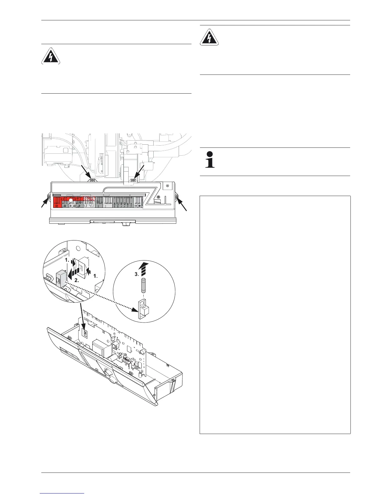
6.6 Replacing the fuse or control panel circuit
board
The fuse is in the switchboard PCB.
Fuse type: 250 V, 4 AT IEC 60127-2/5.
1. Open the boiler control panel and pull out all connection plugs
from the circuit board (see section 6.3, steps 1 - 4).
2. Remove the 4 locking screws on the control panel casing us-
ing a screwdriver (fig. 6-14).
3. Remove the top of the casing.
4. Lift the control panel board out of the bottom part of the hous-
ing.
5. Replacing the fuse or control panel circuit board (fig. 6-15).
6. Replace the control panel circuit board into the housing bot-
tom section.
7. Replace top of casing.
8. Insert all connectors on the switchboard PCB. Close boiler
control panel.
6.7 Wiring diagram
Tab. 6-1 Legend for fig. 6-16
WARNING!
Live parts can cause an electric shock on contact and
cause life-threatening burns and injuries.
Ɣ Before beginning work on live parts, disconnect
them from the power supply (switch off fuse, main
switch) and secure against unintentional restart.
Fig. 6-14 Remove the locking screws from the control panel casing
Fig. 6-15 Changing the fuse
CAUTION!
Electrostatic charges can lead to voltage arcing that
can destroy the electronic components.
Ɣ Secure potential equalisation before touching the
control panel circuit board (e.g. by touching the
control panel mounting).
If the fuse immediately blows upon switching on again,
there is a short circuit in the electrical system. Have a
professional electrician remedy the cause of the short
circuit before putting in a new fuse.
1 Mains switch
2 Operating part RoCon B1
16 Switchboard PCB
17 Communication cable (switchboard PCB - operating section)
18 Stickers for connection assignment
19 Heating circulation pump
20 Gas burner
21 Automatic firing CM124
22 Flow temperature sensor
23 Return flow temperature sensor
24 Flue gas temperature sensor
25 Pressure sensor
26 External temperature sensor
27 Storage tank temperature sensor*
28 3-way diverter valve
J1 3-pin circuit board connector with pump cable mains)
J2 4-pin circuit board connector with valve cable
J3 6-pin circuit board connector (not occupied)
J5 3-pin circuit board connector with pressure sensor cable
J6 4-pin circuit board connector with clamped mains cable and earth-
ing slots
J7 2-pin circuit board with PWM signal cable for heating circulation
pump
J8 12-pin circuit board connector to connect sensorsand control lines
flue gas temperature sensor is connected)
J9 5-pin circuit board connector (not occupied)
J10 3-pin circuit board connector with mains cable for automatic firing
CM124
J11 5-pin circuit board connector with mains cable for automatic firing
CM124
J12 4-pin circuit board connector (not occupied)
J13 4-pin circuit board connector for connecting additional regulating
system components (CAN-Bus)
J14 3-pin circuit board connector for clamping a circulation pump
J15 4-pin circuit board connector with switch cable
J16 4-pin circuit board connector for connecting a room thermostat
(digital demand contact)
* Accessories