4 x Set-up and installation
FA ROTEX A1 BGe - 02/2014
9
4 Set-up and installation
Incorrect set-up and installation would render the manufacturer's
guarantee for the unit void. If you have questions, please contact
our Technical Customer Service.
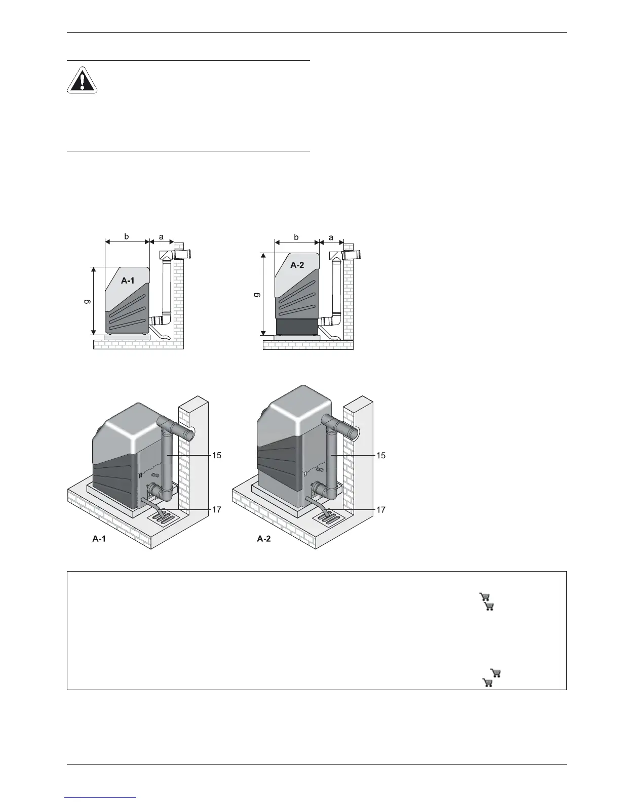
4.1 Dimensions and connection dimensions
Tab. 4-1 Legend from fig. 4-1 to fig. 4-3
WARNING!
Units which have been set-up and installed incorrectly
may not operate properly and can be a health and
safety risk endangering human life.
Ɣ Erection and installation of the ROTEX heat
generator only by authorised and trained heating
experts.
Fig. 4-1 Dimensions of model variants, side view (legend see tab. 4-1)
1 Boiler return (1" AG)
2 Boiler flow (1" AG)
3 Filling line connection on the KFE cock
1)
(½" AG)
4 Flue gas/air intake connection (DN 80/125)
5 Connection expansion vessel
1)
(½" IG)
6 Burner
7 Safety valve
1)
( ½" IG, flue line ¾" IG)
8 3-way diverting valve
2)
(1" AG)
9 Hot water (¾" IG)
10 Circulation (¾" IG)
11 Heat exchanger return (¾" AG)
12 Sensor immersion sleeve
13 Heat exchanger flow (¾" AG)
14 Cold water (¾" IG)
15 Air/flue system (LAS) - Connection piece
(DN 80/125)
16 Air inlet hose (DN 50)
17 Condensate drain hose (DN 40)
A-1 ROTEX A1 BG 25(F)-e
A-2 ROTEX A1 BG 40(F)-e
B Boiler frame KU ( 15 30 21)
C Sub-tank US 150 ( 16 01 52)
AG Male thread
IG Female thread
a - k Dimension see tab. 4-2
1)
Accessory SBG A1 ( 15 60 18)
2)
Accessory VSA1 ( 15 48 22)