15 x For the chimney sweep
15 For the chimney sweep
15.1 Data for designing the flue gas pipe
Tab. 15-1 Triple values for chimney design (flue gas flow dependent on
heat output, see fig. 4-6, page 15)
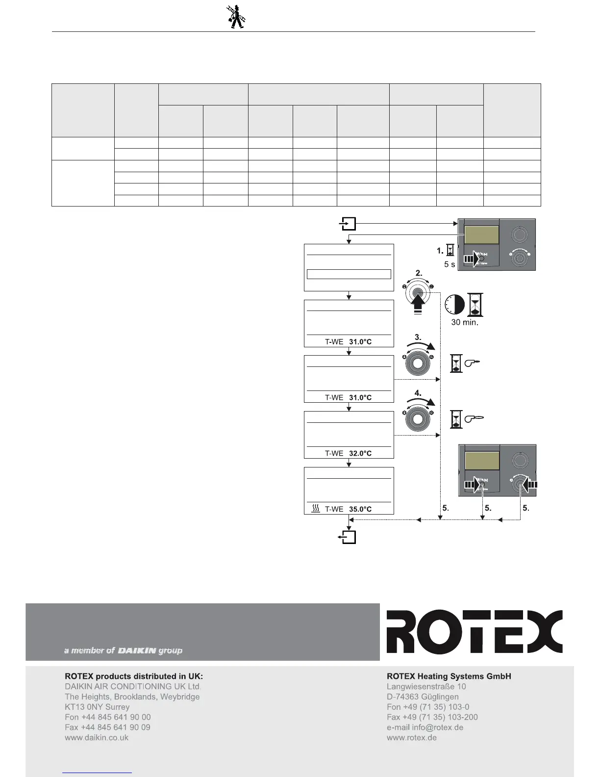
15.2 Emissions measurement
The check measurement can be made by a simply selectable automatic
function (see also "Operating Instructions - ROTEX-RoCon BF Con
-
troller").
Ɣ Depress the exit button for at least 5 secs.
Î Menu "Special Level" is displayed.
Ɣ Select the programme "Emission Measurement" with the rotary
switch.
Ɣ Confirm the changes with a brief push of the rotary switch.
Î The following load types are available for selection:
– Off: Emission measurement is switched off, any Gas condensing
boiler-connected heat generator that is switched on continues to
be regulated normally.
– Base Load: The heat generator is switched on and operated at
the minimum output of the heat generators, irrespective of the set
operating mode.
– Full Load: The heat generator is switched on and operated at the
maximum output of the heat generators, irrespective of the set
operating mode.
Ɣ Select the load type "Full Load" using the rotary switch, but do not
confirm it.
Î Display: "Full Load"
Î The burner is turned on for 30 min. and is regulated at maximum
load.
Ɣ Select the load type "Base Load" using the rotary switch, but do not
confirm it.
Î Display: "Base Load"
Î The modulating gas burner runs at minimum output for 30 mins.
Ɣ Cancellation and jump back by:
– Pushing the exit button or rotary switch again
– Selection of a different menu using the rotary switch and confirma-
tion.
Unit Burner-
load in
kW
Rated output in kW Flue gas mass flow in g/s Flue gas temperature
in °C
Available
pumping
pressure in
Pa
40/30 °C 80/60 °C Natural
gas E/H
Natural
gas LL/L
Liquefied
petroleum
gas
40/30 °C 80/60 °C
A1 BG 25(F)-e
5.5 6.0 5.5 2.31 2.31 2.09 32 58 30
25.7 27.0 25.0 10.79 10.81 9.77 45 79 200
A1 BG 40(F)-e
8.0 8.5 7.9 3.36 3.37 3.04 34 60 40
30.0 31.4 29.0 12.60 12.62 11.41 43 78 200
35.0 36.6 33.6 14.70 14.73 13.31 45 80 200
42.5 44.2 40.0 17.85 17.88 16.16 48 82 200
Fig. 15-1 Symbolic brief instructions for emission measurement