7 x Gas burner
FA ROTEX A1 BGe - 02/2014
31
7 Gas burner
7.1 Design and brief description
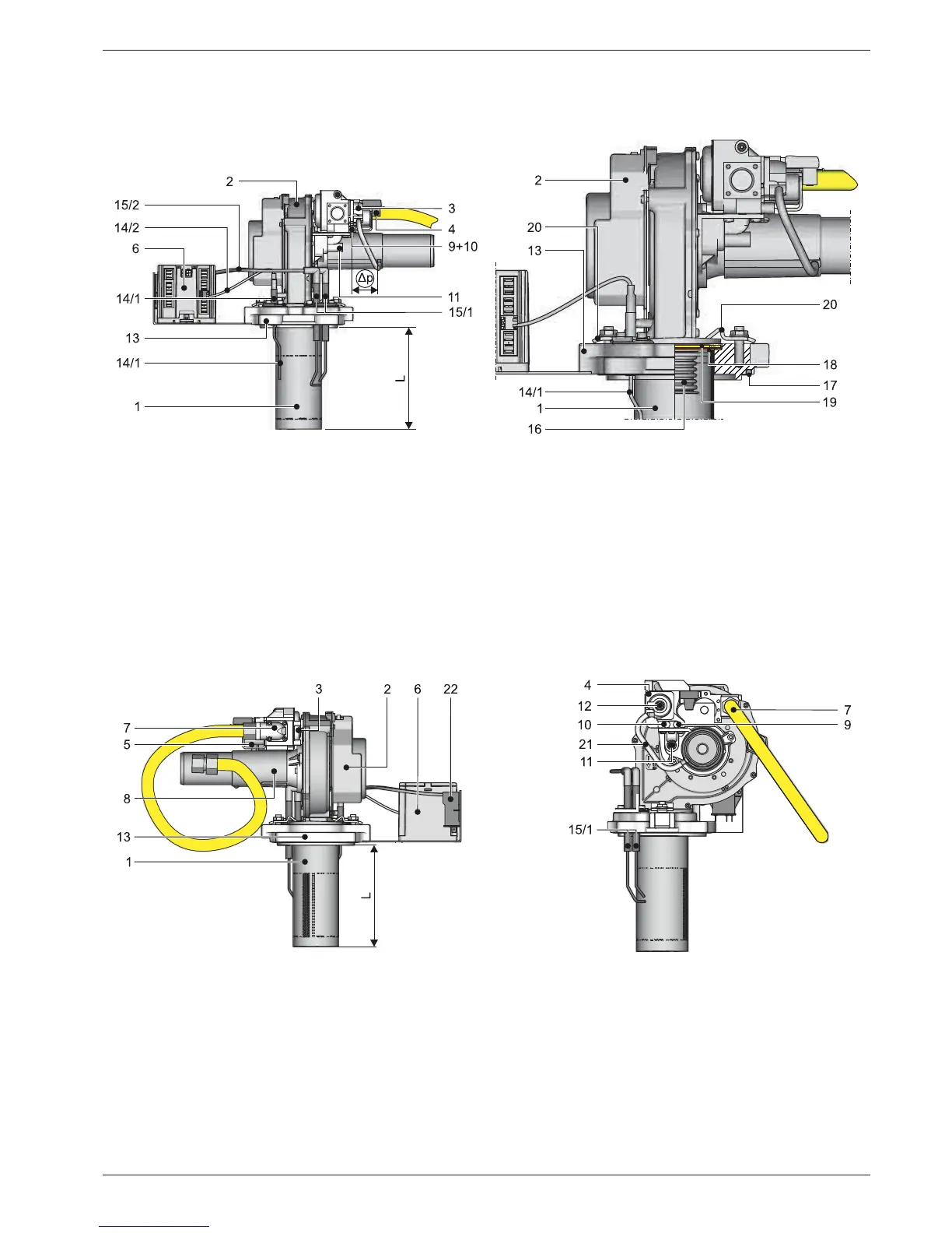
1 Burner surface (flame pipe)
L Flame pipe length: A1 BG 25(F)-e: 157 mm
A1 BG 40(F)-e: 188 mm
2 Blower
3 Safety gas control block
4 Gas/air combination controller
5 Gas solenoid (1 class B and 1 class C)
6 Automatic gas firing CM124
7 Gas connector G ½" IG with corrugated gas connection hose con-
nected
8 Venturi nozzle with DN 50 air connector
9 Measurement connection IN - input gas pressure
10 Measurement connection OUT - output gas pressure
11 Gas/air mixture set screw
12 Gas pressure controller set screw (beneath cover cap)
13 Burner flange
14/1 Ionisation electrode
14/2 Ionisation cable
15/1 Ignition electrodes
15/2 Ignition cables
16 Flame pipe insert
17 Burner flange seal (O ring)
18 Flame pipe seal (graphite gasket)
19 Blower flange seal (silicone gasket)
20 Terminal plate
21 Air intake pressure hose
22 Ignition transformer
Fig. 7-1 Burner of the A1 BG - front view
Fig. 7-2 Burner of the A1 BG - rear view (legend in fig. 7-1) Fig. 7-3 Burner of the A1 BG - left side view (legend in fig. 7-1)