7 x Hydraulic system integration
60
FA ROTEX Solaris - 08/2007
Tab. 7-2 Short names in hydraulic drawings (2)
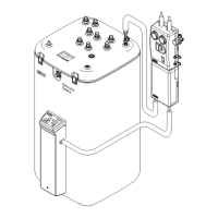
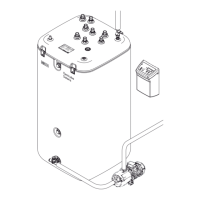
Connection of a pressurised solar panel system
If the building conditions do not allow installation of the solar panels above the storage container, or if the connection pipe cannot
be installed with a continuous gradient between solar panel array and storage container, the non-pressurised Solaris system
cannot be used. A conventional pressurised solar panel system operated with antifreeze can be integrated in a ROTEX heating
system with a Solaris Sanicube or the Gas Solar Unit as follows:
• Integrate the pressurised solar panel system by means of an external plate heat exchanger (Fig. 7-10).
• Connect the pressurised solar panel system to the primary circuit.
• Connect the secondary circuit via the control and pump unit, and operate it without pressure.
• As no great heights are involved in this case, the booster pump P2 can be removed from the RPS3, and used as a solar
circulation pump. For this, the booster pump must be connected in parallel with the circulation pump P1.
• Operate the solar system with the Solaris control unit. For this, a solar panel temperature sensor with a Pt 1000 element is
required (can be ordered optional).
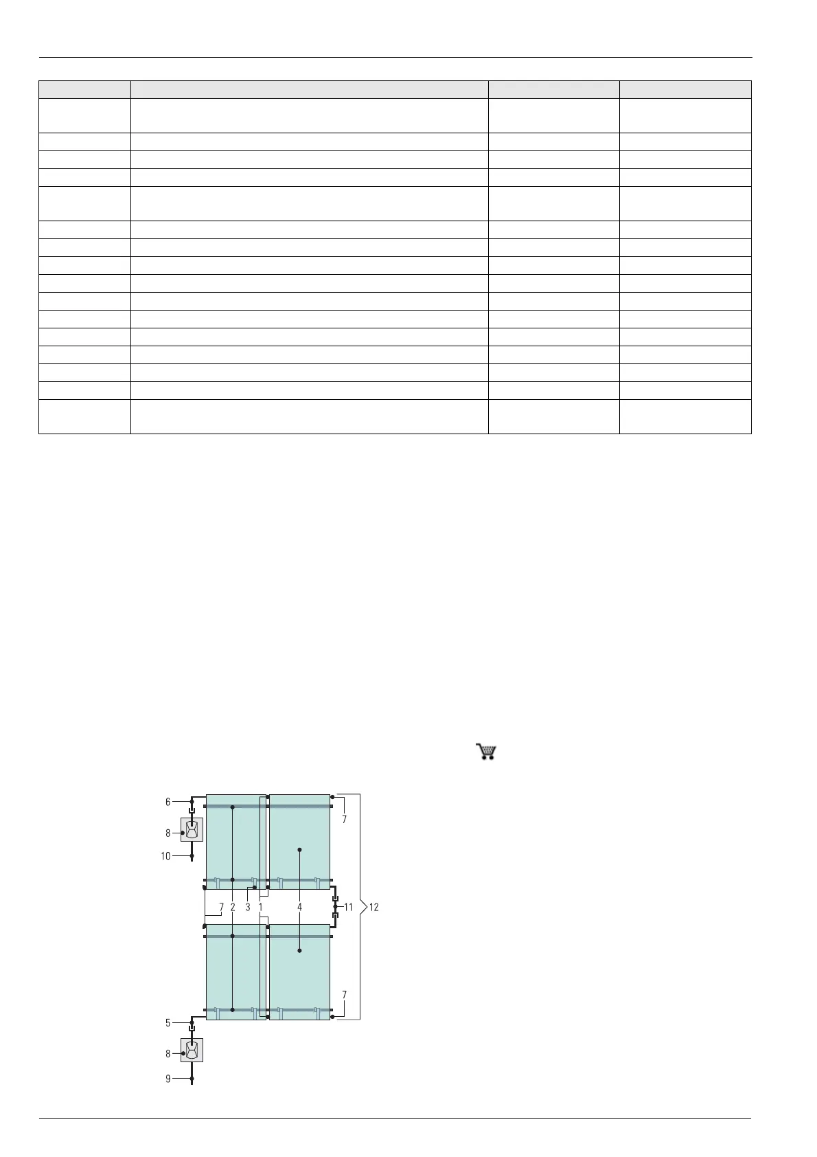
Series connection
As an alternative to the purely parallel solar panel installation described in this manual (also see Fig. 2-1), maximum 3 rows of
solar panels can also be mounted above each other. With such an arrangement, the solar panels or solar panel arrays must be
connected in series (Fig.7-12). One set of series connectors CONRV ( 16 42 17) is required per additional row of solar panels
for the selected solar system.
Fig. 7-12 Alternative solar panel arrangement
Name Meaning Remark Order No.
FLS
Flow sensor, Solaris FlowSensor
(through-flow and flow temperature measurement)
Accessory 16 41 07
FLG Solaris FlowGuard regulating valve with flow indicator 16 41 02
VS Anti-scald guard VTA 32 Accessory 15 60 15
ÜV Overflow valve on site
WEx External heat generator
(e.g. wood pellet boiler, other solid matter boiler, heat pump)
on site
P
WEx
Pump for external heat exchanger circuit on site
RTA Return flow temperature accentuation if needed
PWT Plate heat exchanger on site
MV Two-way solenoid valve
P
B
Swimming pool circuit pump
t
B
Swimming pool temperature sensor
TMV Thermostatic 3-way valve for the return flow temperature accentuation on site
DTR Difference temperature control on site
t
1
Heating return flow temperature sensor suitable for DTR
t
2
Buffer storage temperature sensor suitable for DTR
Disconnection of the standard connection – PK must be removed from the
device and reconnected outside the device
on site
1 Solar panel connector
2 Mounting rail
3 Solar panel securing clip
4 Solaris flat solar panel
5 Return flow connection solar panel
6 Feed connection solar panel
7 Solar panel sealing cap
8 Roof ducts for feed/return flow
9 VA 18 Solar return flow pipe
10 VA 15 Solar feed pipe
11 Solar panel series connector CON RV
12 Solaris solar panel (2x 2 solar panels)