Operating Instructions 7 SG9M Manual
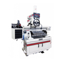
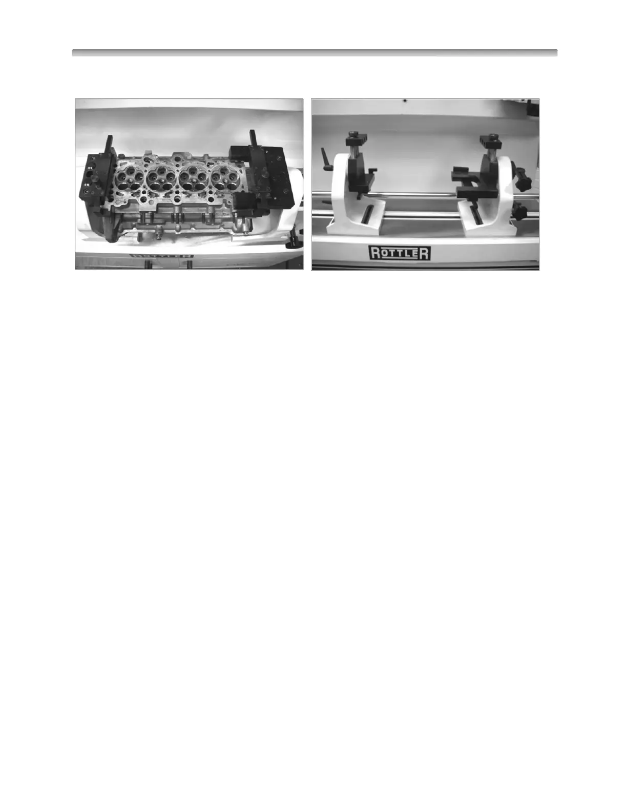
On This cylinder head they using both style frames
Alignment and Setup:
Alignment and setup applies to both the cylinder head and the machine’s floating head. The goal is to
perfectly align the spindle centerline to the centerline of the area of the head to be machined. Most
machining operations on cylinder heads use the valve guide centerline as the reference point so we will
use that as an example.
IMPORTANT: think of the digital electronic level as a comparator. Because the leveling pin is square to
the machines spindle, as long as you achieve the same readings front to rear and side to side then the
spindle will be in perfect alignment.
Rotate Level 180º to check on the display if the Level is properly adjusted. If Level does not read same,
adjust the digital Level; See Calibrating the Digital Level section on this manual and follow steps.
Front to Rear Cylinder Head Alignment:
Position the level on level pin to read front to rear and take a reading. Rotate the cylinder head so that the
valve seats are facing up. Now place the level on a pilot in the cylinder head and position the level to read
front to rear. Loosen the lock levers on the supports. Be certain the fine adjustment lock screw is
loosened. Coarse adjustment is made by turning the work piece manually, until the level reading is within
a couple of degrees of the reading on the leveling post.
Lightly tighten the lock levers on the supports to remove any play. Now tighten the clamp on the fine
adjustment screw. Turn the adjustment knob to achieve the exact reading that was observed on the
leveling post. You can now completely tighten both the left and right support locks.
Note: An optional alignment bar is available that helps establish the front to back alignment on canted
valve cylinder heads. The bar is held against two pilots in two adjacent guides. Use the alignment post to
adjust the angle.
Left to Right Alignment:
Obtain the left to right reading from a pilot mounted in a guide in the cylinder head. Now place the level on
the leveling post. Loosen both of the tilt lock levers on each side of the quill housing. Use the tilt adjusting
hand wheel to adjust the reading to be the same as that found on the pilot in the cylinder head. Tighten
the tilt lock levers.
Note: Alignment tolerance for core drilling is plus or minus .04 degrees, for forming three angle
seats is plus or minus .08 degrees.