Publication date: Jan., 2009
Revision A1
14
2-1-3-3. Switch Cascading in Topology
• Takes the Delay Time into Account
Theoretically, the switch partitions the collision domain for each port in switch
cascading that you may up-link the switches unlimitedly. In practice, the network
extension (cascading levels & overall diameter) must follow the constraint of the
IEEE 802.3/802.3u/802.3z and other 802.1 series protocol specifications, in which
the limitations are the timing requirement from physical signals defined by 802.3
series specification of Media Access Control (MAC) and PHY, and timer from some
OSI layer 2 protocols such as 802.1d, 802.1q, LACP and so on.
The fiber, TP cables and devices’ bit-time delay (round trip) are as follows:
1000Base-X TP, Fiber 100Base-TX TP 100Base-FX Fiber
Round trip Delay: 4096 Round trip Delay: 512
Cat. 5 TP Wire: 11.12/m Cat. 5 TP Wire: 1.12/m Fiber Cable: 1.0/m
Fiber Cable : 10.10/m TP to fiber Converter: 56
Bit Time unit : 1ns (1sec./1000 Mega bit)
Bit Time unit: 0.01μs (1sec./100 Mega bit)
Table 2-2
Sum up all elements’ bit-time delay and the overall bit-time delay of
wires/devices must be within Round Trip Delay (bit times) in a half-duplex network
segment (collision domain). For full-duplex operation, this will not be applied. You
may use the TP-Fiber module to extend the TP node distance over fiber optic and
provide the long haul connection.
• Typical Network Topology in Deployment
A hierarchical network with minimum levels of switch may reduce the timing
delay between server and client station. Basically, with this approach, it will
minimize the number of switches in any one path; will lower the possibility of
network loop and will improve network efficiency. If more than two switches are
connected in the same network, select one switch as Level 1 switch and connect all
other switches to it at Level 2. Server/Host is recommended to connect to the Level
1 switch. This is general if no VLAN or other special requirements are applied.
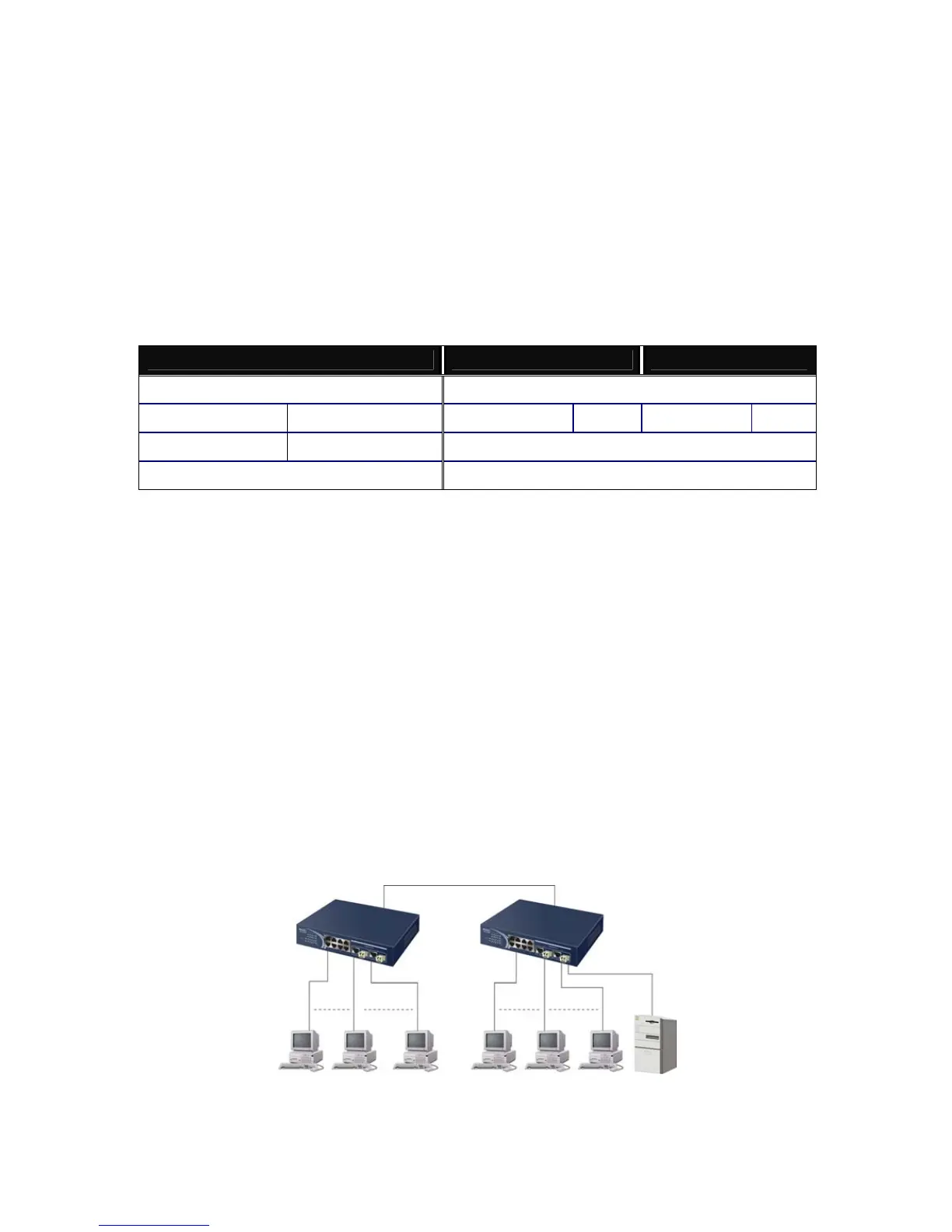
Case1: All switch ports are in the same local area network. Every port can access
each other (See Fig. 2-3).
If VLAN is enabled and configured, each node in the network that can
Fi
 Loading...