VLT
Vertical Process Pump
38 V1.090418
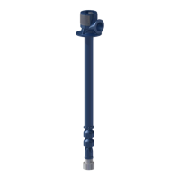
Figure 5.3. Motor shaft extension relative to the pump shaft center line.
Now with the indicator bracket attached to the pump hub reading off the motor hub, rotate unit
again in 90° increments. NOTE: If you can set up both indicators at once, both sets of readings can be
taken at one time.
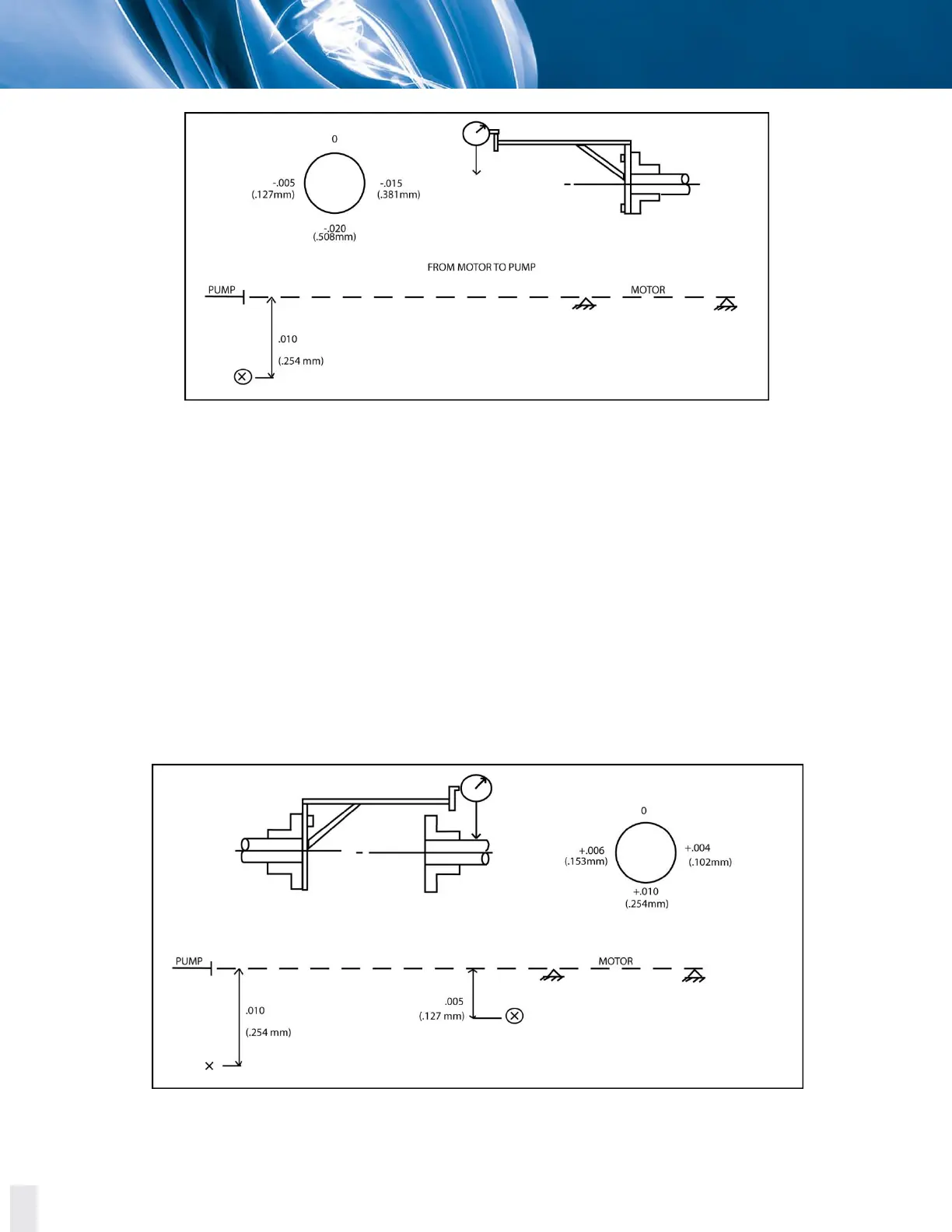
Bottom reading is then corrected for indicator sag. The -0.005 inch (-0.127 mm) was subtracted from
the +0.005 inch (+0.127 mm) indicator reading to give an actual +0.010 inch (+0.254 mm) reading.
The +0.010 inch (+0.254 mm) is divided by two to give +0.005 inch (+0.127 mm) which is the actual
shaft extension to shaft relationship.
In this case, a plus reading at the bottom indicates the motor shaft is low compared to the pump
shaft extension. Plot this point as shown in the example.
Figure 5.4. T.I.R. second reading