VLT
Vertical Process Pump
39 V1.090418
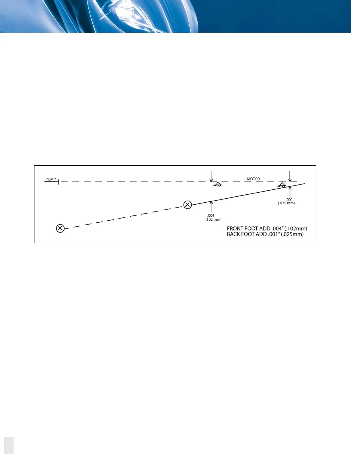
We have now located the motor shaft theoretical extension in two places:
A. In the plane of the pump hub.
B. In the plane of the motor hub.
Drawing a straight line through these two points crossing the plane of the two motor feet. The shim
adjustment can now be read directly off the graph. In this example, 0.004 inch (0.102 mm) should be
added to the front foot and 0.001 inch (0.025 mm) should be added to the back foot.
This solution can also be done by the use of pre-programmed, hand calculators for faster results.
For the horizontal (side to side) results, the same procedure is used. Algebraically subtract the side to
side readings. Indicator sag can be ignored as it cancels out. Plot these readings and the results can
be read off the graph plot.
Figure 5.5. Final graph plot for reverse indicator alignment graphical analysis.
C. REVERSE INDICATOR ALIGNMENT MORE THAN TWO UNITS GRAPHICAL ANALYSIS
This method lends itself very well in solving alignment problems of three or more pieces of
equipment in a line.
To solve this problem, follow the steps already outlined for each coupling in the train. Plot the shaft
to shaft relationship of each set of shafts. Look at the total picture. In this example, a line was drawn
through the average of all points plotted. The units were then aligned to this mean line.