Revision 4 - December 17,1998 Ryan TCAD 9900 Series Page 1-7
The Sample Description of Work Accomplished (Figure 1-4) is suggested language
provided as a convenience to the installing agency. The information and wording should
be modified to correctly describe the particular installation. Ryan International
Corporation assumes no responsibility for alterations to the airframe.
1.9 ANTENNA CABLE REQUIREMENTS
TCAD measures the signal strength of received transponder replies to estimate distance.
Proper range performance is dependent on correct antenna cable attenuation, which is
directly related to proper cable types, lengths and the quality of the cable terminations.
TCAD is designed for 3±½ dB loss in the antenna cables. In addition, the cable loss of
each cable must match within 0.2 dB (about 12 inches). This is normally accomplished by
keeping the lengths and configurations the same for each cable.
NOTE: Matched antenna cable lengths are important. The top and bottom antenna
cable attenuation should be matched to within 0.2dB.
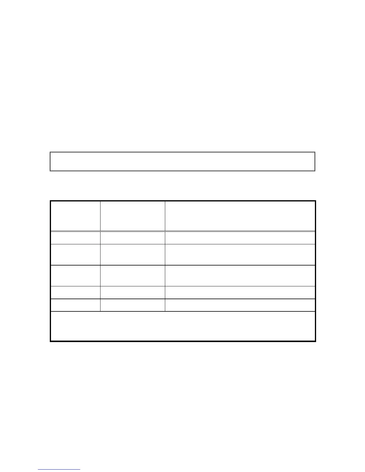
Figure 1-3 identifies recommended cable types. Cables from other manufacturers can be
used. If so, the loss at 1GHz must be supplied and used to calculate the cable length.
Cable Length
to meet 3dB
requirement
Cable Attenuation
(dB/100 feet
@1 GHz)
Recommended Cable
Note: Equivalent cable with proper attenuation
may be used. Contact the cable manufacturer.
15± 2 feet 19.6 ECS* 3C058A
24± 3 feet 13.0 ECS 3C142B, EMTEQ* PFLX175-100 or
PIC* S44191
26± 4 feet 11.5 ECS 311901, EMTEQ PFLX 195-100 or
PIC S44193
35± 5 feet 8.6 ECS 311601
45± 8 feet 6.6 EMTEQ PFLX340-100
*High-performance cables usually require special connectors. Contact the cable
manufacturer for more information. To Contact ECS, call 1-800-ECS-WIRE;
EMTEQ, 888-679-6170; and PIC Wire & Cable 1-800-742-3191.
Figure 1-3 Antenna Cable Requirements
 Loading...