Revision 4 - December 17,1998 Ryan TCAD 9900 Series Page 4-8
4.8 BENCH TEST SET UP
To perform checks of the TCAD on the bench, prepare 15-pin D, 25-pin D and 9-pin D
connectors as follows:
A. Wire the 15-pin D connector by grounding pins 3 and 9. This will
provide a simulated altitude of 6700 feet.
B. Wire power, ground and the display lines between the Display and the
Processor as shown in the wiring diagram in Section II.
C. Connect the audio output to a suitable audio amplifier and speaker.
D. Connect the Display to the Processor.
E. Coupler, Suppression or Antenna connections are not needed for TCAD
operation on the bench.
4.9 TECHNICIAN TEST ROUTINE
Use the following steps to access the Technician Test for the Suppression check. The
button sequence must be done quickly to enter the routine. It is designed to be difficult to
access to insure that operators do not accidentally enable the routine:
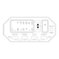
A. Press the following buttons pairs sequentially:
DATA and MUTE, then
TRML and STD, then
DATA and ENRT.
Then press the s button,
then press the t button,
then press the MUTE button.
B. The Display will show the word TESTING, and the code corresponding to
the altitude generated from the aircraft encoder:
TESTING:
ALT>0240
C. Press the DATA button to generate the suppression square wave. The letter S
will show sideways in the right window of the Display, indicating the signal is
being generated.
 Loading...