Revision 4 - December 17,1998 Ryan TCAD 9900 Series Page 2-9
2.12 MECHANICAL INSTALLATION OF TRANSPONDER COUPLER
NOTE: Insure that the transponder antenna cabling is serviceable, and the shielding
is properly secured to the connectors. Poor shielding of the transponder radiation can
cause interference. If there is any question about the condition of the transponder cable,
replace it.
A. The Transponder Coupler can be installed in the avionics bay or behind
the instrument panel, using the mounting holes provided. Mounting
location should be accessible. Use number eight-size screws minimum.
B. The Transponder Coupler can be installed vertically, horizontally, or
upside down.
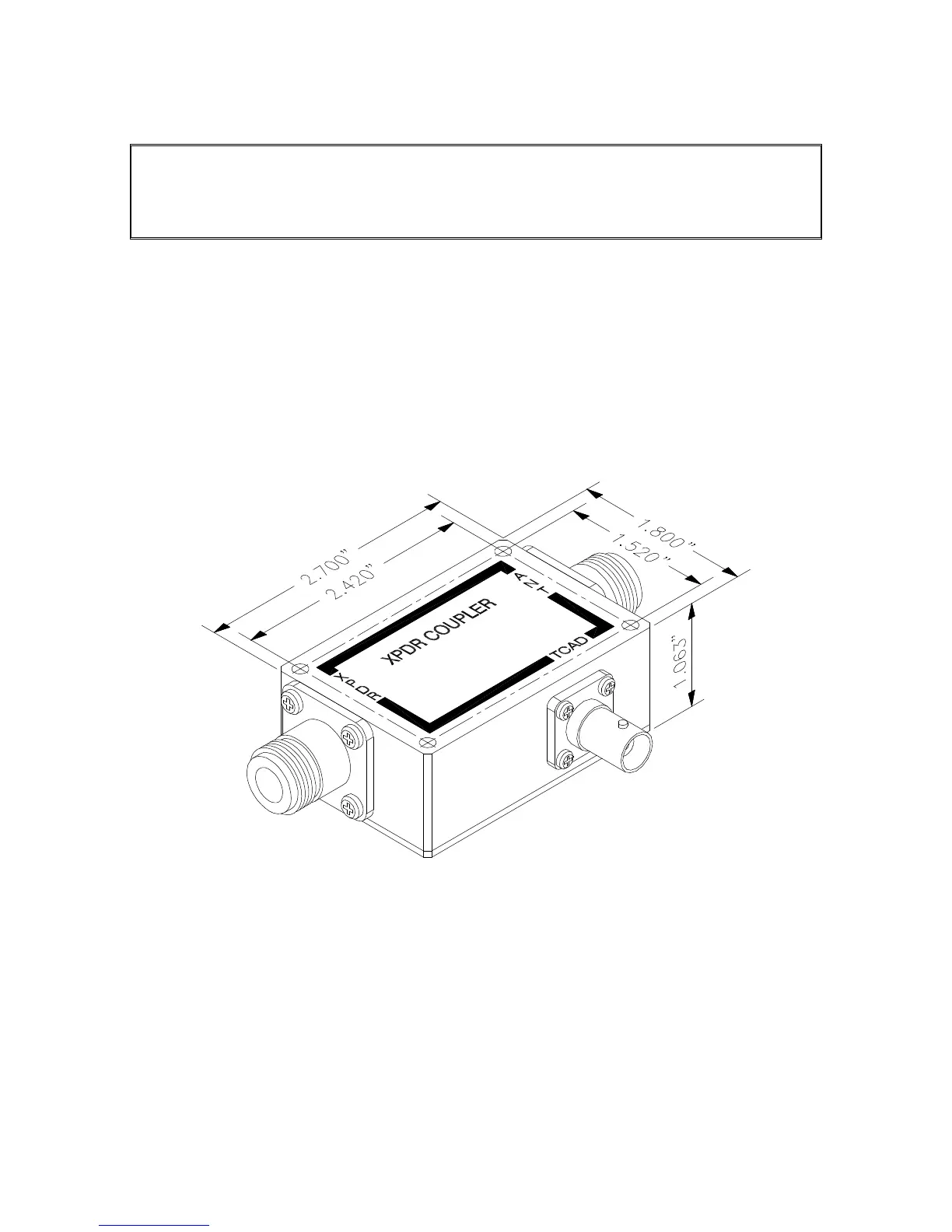
C. See Figure 2-8 for mounting dimensions.
D. Grounding of the coupler is important. Be sure the coupler is well
grounded to the airframe.
Figure 2-8 Transponder Coupler
 Loading...