Revision 4 - December 17,1998 Ryan TCAD 9900 Series Page 2-18
2.16 ELECTRICAL WIRING OF SUPPRESSION
Paragraph 2.4 describes suppression. When a transponder is aboard the aircraft, the
transponder input suppression must meet ARINC standards. Figure 2-2 gives a list of
common transponders and their suppression characteristics. TCAD is compatible with
both mutual and unidirectional suppression systems.
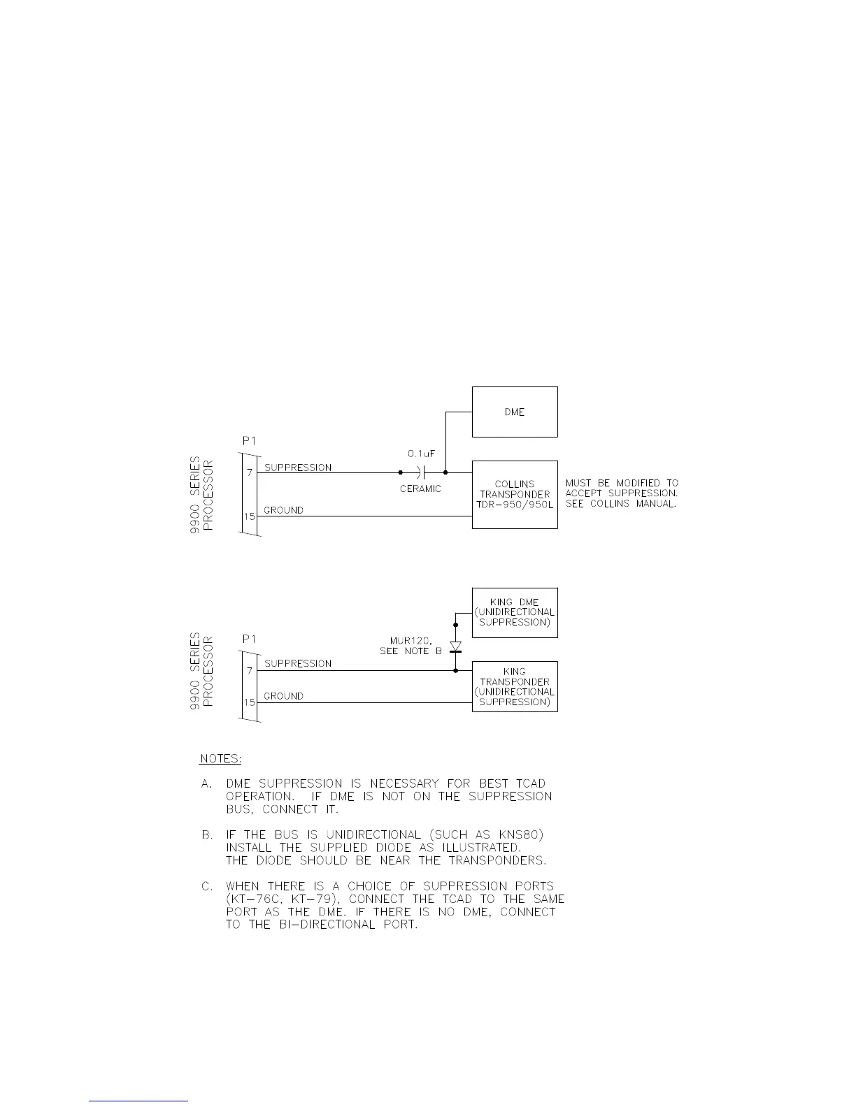
Suppression of DME will assure that the DME does not interfere with the transponder and
reduce data available to the TCAD. If DME is not on the suppression bus, connect it.
Figures 2-14 and 2-15 illustrate normal wiring for transponder and DME suppression.
The suppression characteristics of some transponders and DMEs do not conform to
ARINC standards, but the condition can be corrected with external components. See
Figure 2-16. Most of the components needed are included in the TCAD installation kit.
For more information see Transponder Suppression, Section VI.
Figure 2-16 Suppression Configurations
 Loading...