Revision 4 - December 17,1998 Ryan TCAD 9900 Series Page 2-5
When routing the Coupler Cable, make the run as short as practical, and avoid routing
with any cable that may emit excessive EMI, such as DME, transponder cables,
suppression lines from other equipment or high-current power cables.
When mounting the Transponder Coupler, use the type-N connectors provided. Use of
BNC to Type-N adapters can increase the VSWR in the transponder cabling. Check the
output frequency of the transponder at its antenna after installing the Coupler to
insure that a standing wave has not been introduced.
NOTE: Insure that the mounting location for the coupler is accessible and
at a location that provides a good ground. Normally, the mounting tray or avionics rack is
not a good ground.
2.9 INITIAL BENCH CHECK
Every Ryan TCAD is checked for operation before shipment. Occasionally however, a
unit may not function after shipment. To avoid undue inconvenience, an initial bench
check is appropriate. See Paragraph 4.3 for this procedure.
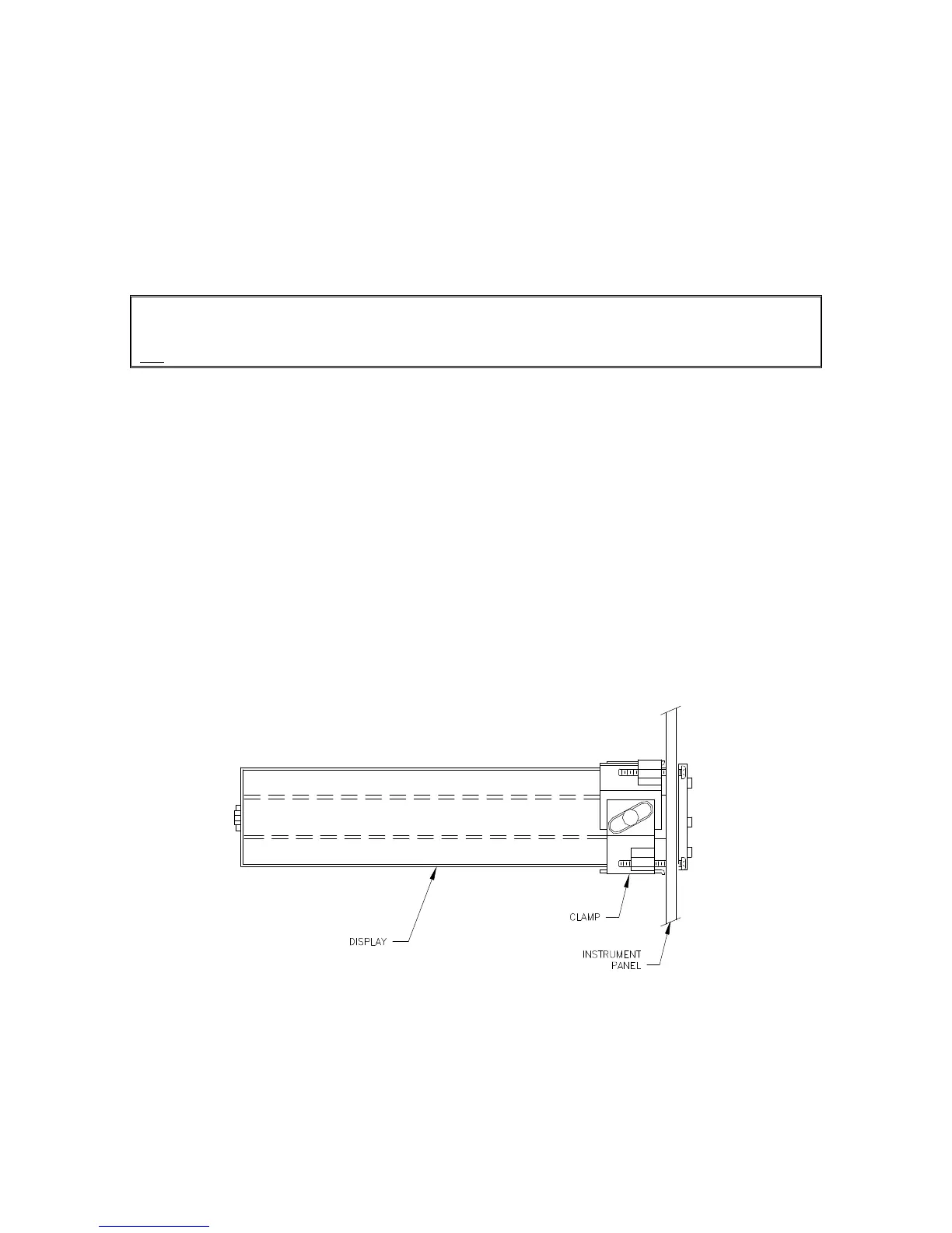
2.10 MECHANICAL INSTALLATION OF DISPLAY
The Display is rigidly mounted in the instrument panel, and is secured using the clamp
provided. Allow adequate space for installation of cables and connectors. Figure 2-3
illustrates the Display mounting, Figure 2-4 gives the Display overall size and Figure 2-5
shows the panel cutout.
CAUTION: When removing the Display, do not pull the ON/OFF switch.
Pull from behind the trim ring of the bezel.
Figure 2-3 Display Mounting
 Loading...