Revision 4 - December 17,1998 Ryan TCAD 9900 Series Page 2-13
2.15 ELECTRICAL WIRING OF DISPLAY AND PROCESSOR
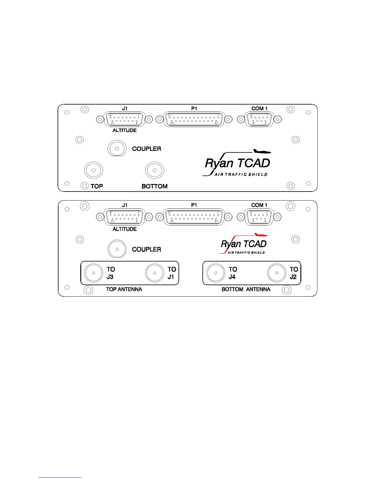
A 25-pin connector marked P1 on the Processor, and the 9-pin connector (P910) on the
Display, interconnect the Processor and Display. The front panel view of the Processor is
shown in Figure 2-11 below, which illustrates the location of P1. P1 is also connected to
devices other than the Display.
Figure 2-11 Processor Front Panel View (9900, 9900A above, 9900B below)
The electrical wiring between Processor and Display(s) is shown in Figure 2-14 and Figure
2-15. Figure 2-14 illustrates wiring for a single transponder and single Display. Figure 2-
15 illustrates wiring for dual transponders or dual Displays. See Paragraph 1.7 for wire
types. Further, referring to Figure 2-14 or Figure 2-15 as appropriate, the battery power,
audio, and annunciator (if used) can be wired. Install a trip-free resettable, 3-Ampere,
circuit breaker between the battery power for TCAD and the aircraft power bus (see
Paragraph 1.7). Audio from the TCAD has a power level of 100 mW into 600 ohms, and
should be connected through the audio panel, typically through an unswitched input. The
use of the annunciator feature is described in Paragraph 2.5. Connection of suppression to
the Processor is described in Paragraph 2.16.
 Loading...