Revision 4 - December 17,1998 Ryan TCAD 9900 Series iv
LIST OF ILLUSTRATIONS
Figure Page
1-1 Features of the 9900 Series .................................................................. 1-2
1-2 Air Traffic Shield Limits....................................................................... 1-4
1-3 Antenna Cable Requirements................................................................ 1-7
1-4 Sample Description of Work Accomplished.......................................... 1-8
1-5 Environmental Qualifications................................................................ 1-10
2-1 TCAD Components ............................................................................. 2-2
2-2 Availability of Suppression for Popular Transponders........................... 2-3
2-3 Display Mounting................................................................................. 2-5
2-4 Display Dimensions.............................................................................. 2-6
2-5 Panel Cutout for Display...................................................................... 2-6
2-6 Processor Mounting Tray..................................................................... 2-7
2-7 Processor with Mounting Tray............................................................. 2-8
2-8 Transponder Coupler ........................................................................... 2-9
2-9 Recommended Antenna Locations ....................................................... 2-10
2-10 Block diagram of Electrical Wiring....................................................... 2-12
2-11 Processor Front Panel .......................................................................... 2-13
2-12 25-Pin Cable-End Receptacle for Mating with P1................................. 2-14
2-13 9-Pin Cable-End Receptacle for Mating with P910............................... 2-15
2-14 Wiring Diagram for a Single Display or Single Transponder................. 2-16
2-15 Wiring Diagram for Dual Displays or Dual Transponders ..................... 2-17
2-16 Suppression Configurations.................................................................. 2-18
2-17 Installing Cables to the Transponder Coupler ....................................... 2-20
2-18 Internal Diode Isolation of Altitude Encoder Lines............................... 2-22
2-19 15-Pin Cable-End Plug for mating with J1............................................ 2-22
2-20 Model 9900B Top Antenna Illustration................................................ 2-23
2-21 Model 9900B Bottom Antenna Illustration .......................................... 2-23
3-1 Display Symbols................................................................................... 3-3
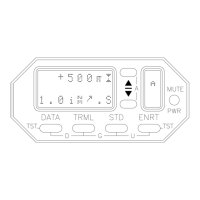
3-2 Controls and Display, Search Configuration ......................................... 3-4
3-3 Controls and Display, Threat Configuration.......................................... 3-5
 Loading...