SOUTHERN AVIONICS COMPANY
Model SA100 Dual 4-23Installation and Operation
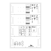
4.4.2.1 Alignment Procedure Standalone Version
1. Ensure:
a. Primary AC / DC power is disconnected.
b. The AC MAIN (CB1), the DC MAIN (CB2) circuit breakers, and the Battery Charger switch
(S1) is in the OFF position.
c. Proper Input / Output connections are made.
d. Front cover is removed and is free and clear of surrounding objects, and secure. Apply AC
power.
2. Using digital multimeter, verify 120/230 VAC is present at the convenience AC Outlet (J1).
3. Connect positive lead of DMM to A1P2.4, and the negative lead to ground.
4. Place battery charger switch (S1) to the ON position.
5. Verify that both the DC O.K., and Power O.K., LED's are illuminated (this may take
approximately 2-10 seconds to occur).
6. Note the voltage at A1P2.4.
7. If necessary, using small flat blade of a plastic alignment tool, adjust the variable resistor
labeled (Adjust 22.5- 28.5) located on the Power Supply ( A1), until a voltage of 28.5 VDC is
measured.
8. Place the battery charger switch (S1) to the OFF position.
9. Connect DMM, (+) to TB2.7, (-) to TB2.8 or across R1.
Warning!
Read and be familiar with these procedures before
attempting maintenance on the LCBC.
Warning!
There are no user serviceable components internal
to the LCBC.
Some procedures will require partial disassembly of the LCBC and
exposure to connections and components that will have potentially lethal
levels of voltage and current applied. In the disassembled state, the
normal safeguards for personnel protection against the hazards inherent
to electrical and electronics equipment will be defeated.