SOUTHERN AVIONICS COMPANY
Model SA100 Dual4-28 Installation and Operation
4.6 Transmitter Check
1. Switch PRI POWER ON. (Primary transmitter if dual system.)
2. Switch RF ON.
3. Adjust RF LEVEL to 20% rated power.
4. Set RF METER switch to REFL. Reading should be zero or very small.
5. Set RF METER switch to FRWD. Adjust RF LEVEL for rated power.
6. PA Voltage should be approximately 60V for all PA's.
7. Set PA READ to CURRENT. PA Current should be approximately 1.8A for all PA's.
8. Set RF METER switch to SET. Adjust METER SET To SET line.
9. Set RF METER switch to READ. Set MODE switch to CONT. Adjust MOD for 95% reading.
10. Set MODE switch to CARR and turn RF LEVEL fully CCW. Switch RF and PRI POWER
OFF.
11. With a dual system, repeat this section for the second transmitter.
4.7 Antenna Tuneup
Install the antenna according to the Antenna Installation manual.
1. Change the jumper on TB3 from dummy load to RF out (if the internal dummy load was
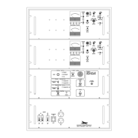
used). Do this on both transmitters for a dual system. (See figure, "Transmitter Diagram SA
Series Rack Mount."
2, Check that the RF LEVEL control is fully CCW and that the MODE switch is in CARR.
NOTE: Autotune is disabled during modulation. If the MODE switch is in CONT (continuous
tone), the system will not tune.
3 Refer to the appropriate user manual for the Coupler being installed for General descriptions,
Coupler specifications, Theory of operation, Coupler setup, Antenna tune up, and Coupler
parts lists.
Caution
The internal dummy load is not designed for continuous
operation. Limit full power operation to fifteen (15) minutes.
 Loading...