SOUTHERN AVIONICS COMPANY
Monitor Receiver xvFigures
Figure 2-33. DC Power Supply PWB Diagram (Single Units)..................................... 2-48
Figure 2-34. DC Power Supply PWB Schematic (Dual Units) .................................... 2-49
Figure 2-35. DC Power Supply PWB Diagram (Dual Units) ....................................... 2-50
Figure 2-36. DC Choke Schematic ............................................................................. 2-51
Figure 2-37. DCHOKE PWB Diagram ........................................................................ 2-52
Figure 2-38. AC Power Supply Schematic.................................................................. 2-54
Figure 2-39. AC Power Supply Diagram..................................................................... 2-55
Figure 2-40. SA Exciter Control Motherboard Schematic ........................................... 2-56
Figure 2-41. Series Exciter Control Motherboard Diagram......................................... 2-57
Figure 2-42. SA RF Motherboard Schematic.............................................................. 2-58
Figure 2-43. SA Series RF Motherboard Diagram...................................................... 2-59
Figure 2-44. SA Series Transmitter Overall Schematic .............................................. 2-60
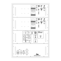
Figure 2-45. Transmitter Diagram SA Series Rack Mount.......................................... 2-61
Figure 2-46. Local Control System Overall Schematic ............................................... 2-64
Figure 2-47. Local Radiobeacon Control Diagram...................................................... 2-65
Figure 2-48. SA Relay 24VDC PWB Schematic......................................................... 2-66
Figure 2-49. SA Relay 24VDC PWB Diagram ............................................................ 2-67
Figure 2-50. Local Control Motherboard Diagram ...................................................... 2-68
Figure 2-51. Page 1 Autotransfer Logic Schematic ................................................... 2-69
Figure 2-52. Page 2 Autotransfer Logic Schematic ................................................... 2-70
Figure 2-53. Autotransfer Logic PWB Diagram........................................................... 2-71
Figure 2-54. Local Transfer Indicator PWB Diagram.................................................. 2-72
Figure 2-55. DC Auto Disconnect ............................................................................... 2-74
Figure 2-56. DC Auto Disconnect Diagram................................................................. 2-75
Figure 2-57. Serial Interface PWB Schematic ............................................................ 2-78
Figure 2-58. Serial Interface PWB Assembly.............................................................. 2-79
Figure 2-59. Modem PWB Schematic......................................................................... 2-80
Figure 2-60. Modem PWB Assembly.......................................................................... 2-81
Figure 2-61. Remote Radiobeacon Control Panel Schematic .................................... 2-82
Figure 2-62. Remote Radiobeacon Control Panel Diagram ....................................... 2-83
Figure 2-63. Remote Transfer Indicator Assembly ..................................................... 2-84
Figure 2-64. Remote Control Motherboard Assembly ................................................ 2-85
Figure 3-1 Antenna Reactance..................................................................................... 3-3
Figure 4-1. Interconnecting Wire Diagram.................................................................... 4-2
Figure 4-2. Input/Output Terminal Blocks ..................................................................... 4-3
Figure 4-1. Load Center/Battery Charger 110V/220V Single Phase(R/M) Overall Sche-
 Loading...