Do you have a question about the Safran LRF 3013 and is the answer not in the manual?
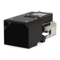
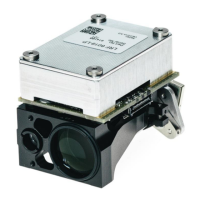
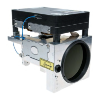
Describes the main components and their functions within the LRF module.
Lists and illustrates the primary physical components of the LRF module.
Details the mechanical and electronic interface definitions of the LRF module.
Explains the fundamental operating principle of the laser rangefinder.
Details the function of the pulsed diode in the rangefinding process.
Describes the semiconductor diode laser and multi-pulse measurement system used.
Details factors affecting range performance, including visibility, albedo, and target properties.
Discusses surface reflectivity and its effect on range performance.
Explains the importance of target angle relative to the laser beam.
Details how object hardness affects accuracy and range.
Warns about potential measurement errors with reflective surfaces.
Explains how vibration affects measurement accuracy and range.
Guides users through the initial setup using the LRF Interface Kit and PC.
Explains how to operate the LRF module using the Safran Vectronix Terminal Software.
Describes how to connect and use the LRF module without the dedicated interface kit.
Provides a checklist for diagnosing and resolving common issues with LRF modules.
Covers safety precautions and procedures for mounting and handling the LRF module.
Offers advice on designing the host system for optimal LRF module integration.
Details surface requirements and material recommendations for mounting.
Provides instructions for securely mounting the LRF module, including screw torque.
Explains the process and tools required for aligning the LRF module's optical axis.
Recommends operating the module in a dry atmosphere to prevent condensation.
Discusses the need for a protective window and its specifications for the LRF module.
Details the Class 1 eye safety requirements and integrator responsibilities.
Describes the system connector type, pinout, and signal functions for communication.
Details power requirements, load capacitance, and timing behavior during measurements.
Specifies the characteristics of the UART serial interface for data exchange.
Explains how the LRF system should be connected to the host system ground.
Outlines how the host system initiates commands and receives answers from the LRF module.
Defines the format and structure of commands sent to and received from the LRF module.
Explains the ACK/NACK characters used for command reception and execution status.
Provides recommendations for serial transmission timing to ensure reliable communication.
Details the various commands for operating the LRF module's functions.
Details the command for performing distance measurements and its output format.
Explains continuous measurement mode and eye safety considerations.
Describes the method for calculating and verifying data integrity using checksums.
Details the command to read out product, version, and hardware configuration information.
Explains how to initiate and interpret the results of the built-in self-test sequence.
Describes the low-power continuous lasing mode and its parameters.
Explains the power-on sequence and the initial ACK signal from the LRF system.
Provides instructions for cleaning the optics and the rest of the LRF module.
Outlines the different service levels and procedures for repair.
Provides design requirements and drawings for the flex cable and system connector.
Contains detailed mechanical drawings and specifications for module mounting.
| Brand | Safran |
|---|---|
| Model | LRF 3013 |
| Category | Measuring Instruments |
| Language | English |