LRF 3013 Integrator Manual
Document number: TML 913655 ver A
Confidential & Proprietary Safran Vectronix AG – All rights reserved
5 HW Interface
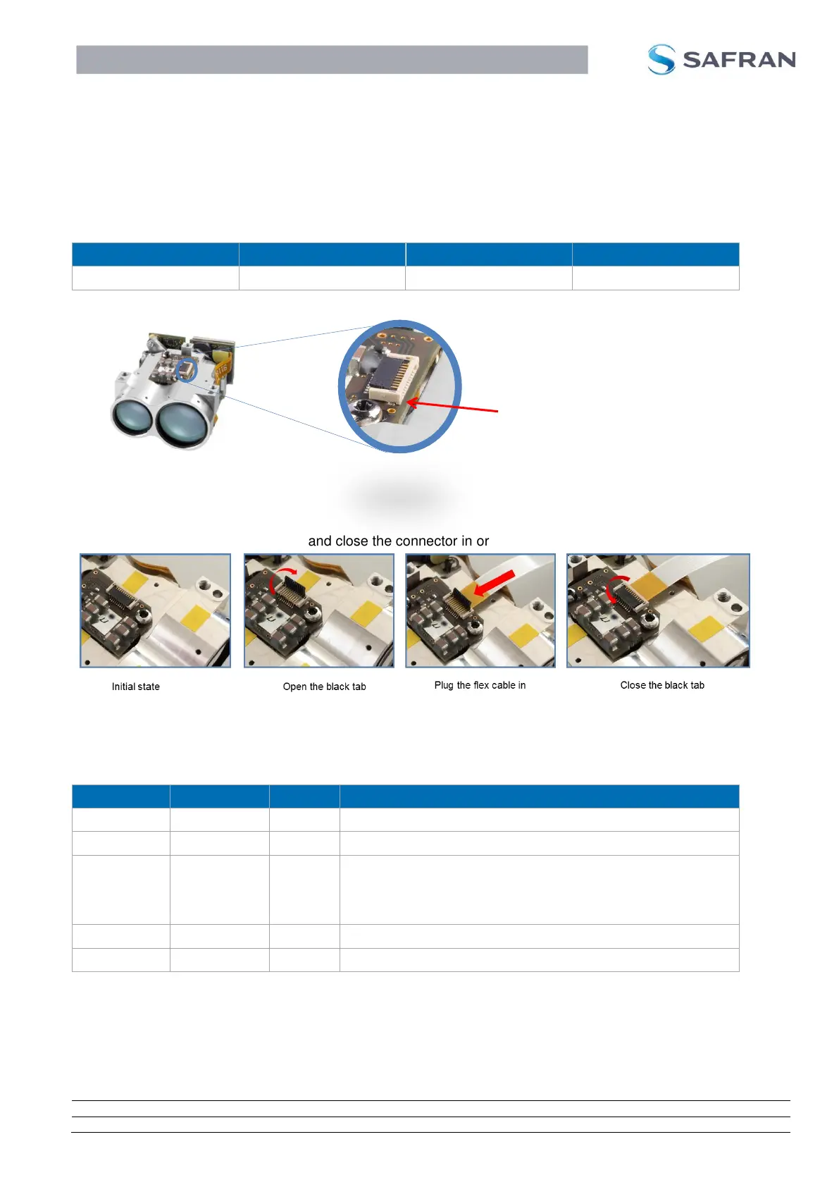
5.1 System Connector and Signal Description
Power supply and communication of the LRF module with the host system is performed via the system
connector. The system connector type is the following:
Figure 12: System connector
Figure 13 below shows how to open and close the connector in order to plug a flex cable in.
Figure 13: How to plug a flex cable in
Following table indicates the system connector’s pin out and the description of each signal.
Connect to the power supply of the system
Connect to the digital GND of the system
High: LRF is ON ( > 2.7V)
Low: LRF is OFF (< 0.3V)
Note: This line integrates a pull-down resistor (100 kOhm)
Transmit line of the UART interface (LRF to host system)
Transmit line of the UART interface (host system to LRF)*
*
Make sure the UART-RX line is in high state if POWER_ON signal changes state LOW to HIGH
Details on the system connector and requirements for the flex cable to the system connector can be
found in the appendix chapter 9.1.
The connector position can be found in the mechanical interface drawing in the appendix chapter 9.2.

 Loading...