Do you have a question about the Safran LRF 6019 and is the answer not in the manual?
Manual is basis for safe use; integrators qualified, users understand instructions.
Notes safety instructions for safe LRF module use. Keep for future reference.
LRF6019 without pointer & LP are Class 1 eye safe laser products.
LRF6019 HP is Class 3B laser product with pointer. Pointer not active is eye safe.
LRF6019 for OEM products only. Avoid modifications; hazardous exposure risk.
The optical fiber is very fragile and sensitive to mechanical stress. If broken, hazardous light emission.
Do not touch, pull, bend or squeeze the optical fiber.
As the LRF module does not perform a plausibility check...
The LRF module is sensitive to electrostatic discharge. Do not touch any electronics.
Do not use the LRF module outside specified limits, power within range, handle in ESD area, etc.
Environmental hazard. Dispose of components as hazardous waste.
Lists inappropriate uses like no plausibility check, modifications, wrong commands, etc.
Inappropriate use may bring the risk of: Misinterpretation of results, Instrument errors, Eye injuries, etc.
Keep packed, remove power, observe temperatures, avoid shocks/transitions.
Perform test measurements on known distances after rough handling.
Manual version C incorporates changes. Information believed accurate for intended use.
Document may not be copied or used for other purposes without written permission.
Safran Vectronix AG provides publication "as is" without warranty of any kind.
Safran Vectronix AG reserves right to revise publication and make changes without notification.
Manual should not be construed as warranty. Changes/variations may exist not reflected in manual.
Descriptions, specs, design were effective at publication time. Subject to change without notice.
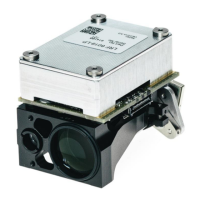
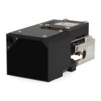
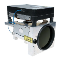
Describes LRF 6019, its versions, and intended users requiring expert knowledge.
Explains emphasis on safety and technical correctness through special formatting.
Defines icons indicating hazards (warning) and important information (notice).
Lists the main components: receiver, transmitter, mainboard, bench, optics.
Explains the operational principle of the pulsed laser rangefinder.
Covers electronics, range capability, visibility, sunlight, object size, albedo, orientation, hardness.
Discusses accuracy issues with mirror-like surfaces and effects of shaking on measurement results.
Instructions for careful unpacking, fiber handling, and ESD precautions.
Recommends using an Interface Kit for PC connection and basic setup.
Step-by-step guide to install the terminal software from the USB stick.
Continuation of software installation: choosing folder, finishing setup, and accepting terms.
Guide on selecting the module, setting interface, and searching for the LRF module.
Steps for finding the module, confirming connection, and returning to the main screen.
Shows log response, notes on clearing log, and connecting without an interface kit.
Precautions for handling the module, protecting against ESD/EMC, and caring for optics.
Refers to appendix for mechanical interface drawing and preparing mounting surface.
Details mounting procedures, alignment tolerances, and surface requirements.
Step-by-step guide for detaching and reassembling the laserbox with flexcable.
Continues laserbox assembly, connecting flexcable and ESD precautions.
Methods for boresighting at 1550/830 nm.
Alternative methods for alignment using poles or laser viewing cards, and nitrogen flushing.
Specifications for front window, antireflection coating.
Recommends tilt angle for front window to prevent sunlight reflections and mentions performance impact.
Details Class 1 and Class 3B safety for LRF models, including hazard distances.
Describes the kit for laboratory use, including filter and protective plate for the fiber.
Identifies the Samtec LSHM connector type and pin count for power and communication.
Details the function of each pin in the system connector.
Covers ESD protection, operating conditions, and voltage requirements.
Lists maximum ratings and electrical characteristics like power consumption.
Details current consumption graphs for powering up and measurement sequences.
Configuration for RS232/RS422 and system grounding concept.
Explains the use of PWR_SAFE for entering OFF Mode and normal operating mode.
Details operating modes, state machine, and communication protocol.
Defines message format, SOM, Product ID, Message ID, and parameters.
Explains checksum calculation, acknowledge, and not acknowledge responses with error IDs.
Specifies timing parameters for commands, wake-up, and start-up delays.
Command to initiate range measurement, returning x targets sorted by merit.
Command to simulate range measurement returning constant targets with fake predefined values.
Command for continuous low power laser emission for alignment purposes.
Command to initiate continuous laser emission at 830 nm for alignment and maintenance.
Command acting as software interlock for laser pointer functionality.
Command to switch between Off Mode, Stand-by Mode, and Normal operating Mode.
Command to initiate a set of x range measurements at 1 Hz repetition frequency.
Command to initiate range requests with predefined repetition rates.
Lists error codes provided by range-related commands for target detection and temperature issues.
Command to set the LRF module's serial interface baud rate.
Command to read out SW version, module type, firmware, hardware, and article number.
Command to set a minimum range threshold value, filtering ranges below it.
Command to set a maximum range threshold value, filtering ranges above it.
Command to retrieve the current minimum or maximum range gate settings.
Command to reset all configuration parameters to their default values.
Command to append timestamp information in microseconds to range measurement commands.
Command to retrieve the current internal clock counter timestamp.
Explains how range commands are affected by timestamp activation parameters.
Command to initiate a built-in test routine for module health assessment.
Command to initiate a power built-in test routine for module health assessment.
Instructions for cleaning optics and the module, including agent warnings.
Outlines service levels and procedures for returning module for repair.
Details the components of the kit for connection, powering, and safety.
Describes the interface cable and its connector pinout diagram.
Provides design requirements for the host system connector mating with the LRF module.
Illustrates various connector mating scenarios and board-to-board connections.
Detailed mechanical drawing showing dimensions, tolerances, and mounting points for the LRF module.
Further details on mechanical interface, including fiber bending radius, connector types, and grounding.
Specifies material, surface treatment, and optical parameters for lenses.
Details the mechanical requirements for the host system connector.
Table mapping decimal, hex, and character representations for UTF-8 encoding.
Lists common abbreviations used in the manual with their full meanings.
| Brand | Safran |
|---|---|
| Model | LRF 6019 |
| Category | Measuring Instruments |
| Language | English |