LRF 6019 Integrator Manual
914928_TML_LRF6019_en_Version C
Confidential & Proprietary Safran Vectronix AG – All rights reserved
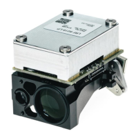
1.2 Interface parts
The mechanical interface of the LRF module base plate is defined by:
a three point mounting base with three threaded holes
two positioning holes
The electronic interface of the LRF module is defined by one system connector for power supply and
communication.
2 LRF Background Information
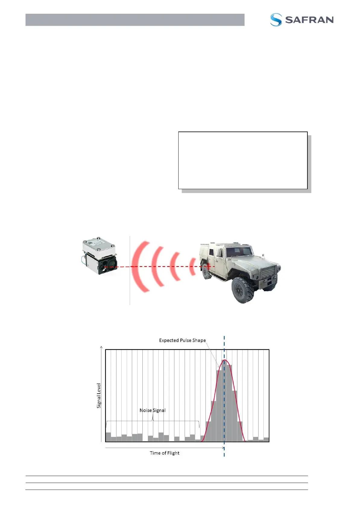
2.1 Rangefinder Principle “Pulsed LRF”
When the laser rangefinder is activated, a series of
laser pulses from the transmitter are sent through the
objective lens to the target. For a good result, most of
the laser pulses have to hit the target.
The main part of the laser light is absorbed or diffusely
reflected by the target and only very small percentage
of the light is reflected back to the LRF module. This
remaining laser light is received by the opposite
objective lens and focused on the receiver diode. The receiver diode (detector) starts sampling the echo
at a very high frequency.
Figure 3 below indicates how laser pulses are emitted from the transmitter, reflected at the target and
sampled by the receiver.
Figure 3: Pulsed LRF – Laser Pulses
The following Figure illustrates the sampled signal of the receiver diode. This information is used to
calculate the distance.
Figure 4: Sampled signal at the receiver diode
Measurement time (return flight) = 6.66 µs
Time of flight (one way) = 6.66 µs / 2 = 3.33 µs
Slope Distance r = light speed x time of flight
= 300 000 km/sec x 3.33 µs ≅ 1000 m
 Loading...