LRF 7047- Integrator Manual
914929_TML_LRF7047_en_Version B
Confidential & Proprietary Safran Vectronix AG – All rights reserved
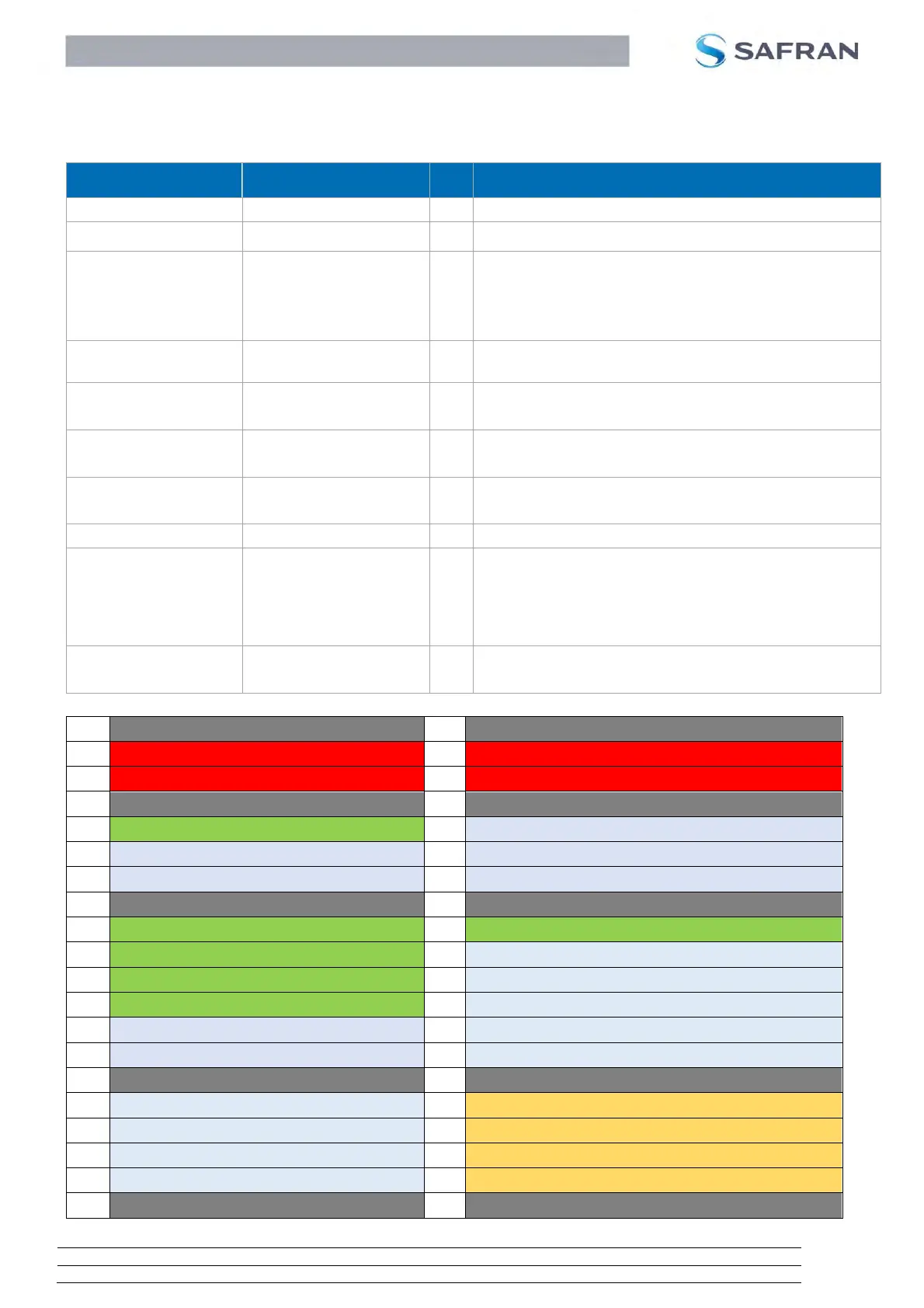
5.2 Pin descriptions
The following two tables indicate the system connector’s pin out and the description of each signal.
1,2,7,8,15,16,29,30,39,40
Connect to digital ground of the system
Optional Signal (see chapter 5.9)
Low or Floating (internally connected to low) normal
operating mode
High OFF mode is activated
RS422 Transmitter positive output line
(from LRF to host system).
RS232/422 Interface Select
Floating RS232
GND RS422
RS232 transmitter line
RS422 negative transmitter line
RS232 receiver line
RS422 positive receiver line
RS422 Receiver negative input line (from host system to LRF).
These pins shall be used to avoid unintended activation of the
non-eyesafe pointer. Interlock pins have to be short circuited to
each other to enable pointer activation with the corresponding
SW command (See chapter 6.5.4). If these pins are not
connected, the pointer cannot be activated.
10,11,12,13,14,20,22,24
25,26,27,28,31,33,35,37
do not connect // leave open
do not connect // leave open
do not connect // leave open
do not connect // leave open
do not connect // leave open
RS232/RS422 Interface Select
do not connect // leave open
do not connect // leave open
do not connect // leave open
do not connect // leave open
do not connect // leave open
do not connect // leave open
do not connect // leave open
do not connect // leave open
do not connect // leave open
do not connect // leave open
do not connect // leave open
 Loading...