FP5/GP5 User’s Manual 19
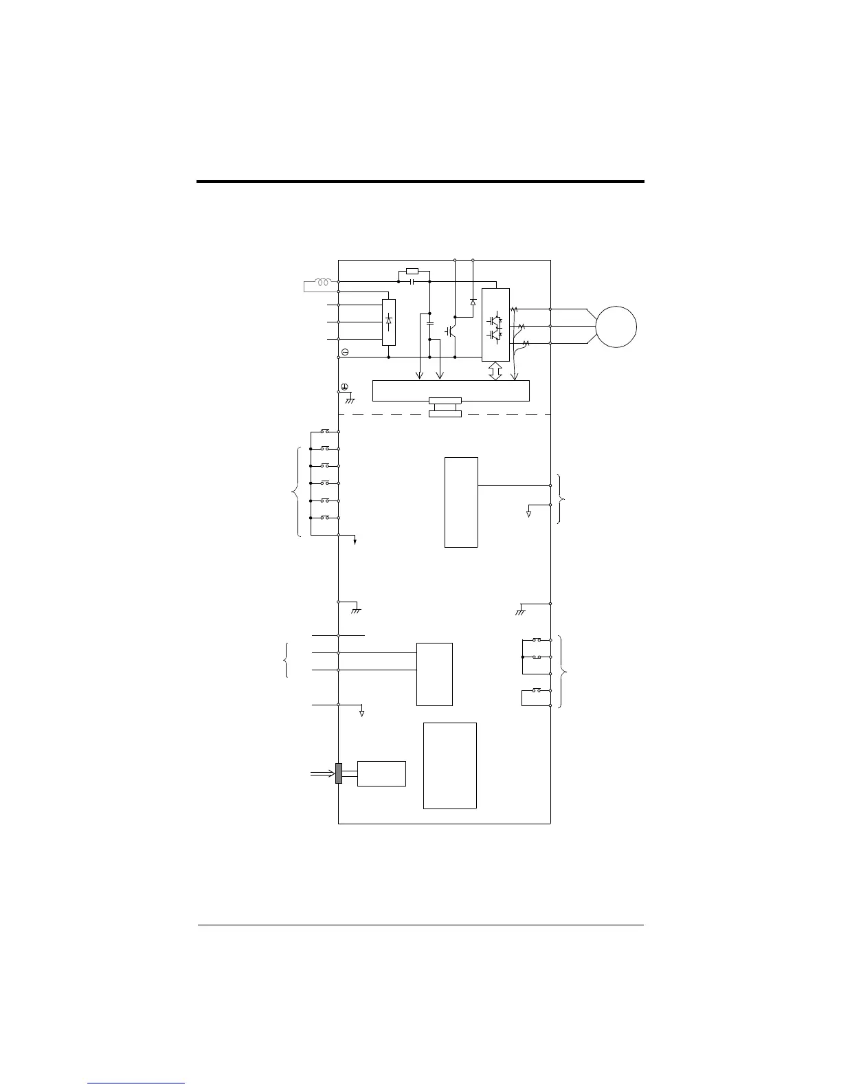
FP5/GP5 Standard Connection Diagram
Figure 9 FP5/GP5 Terminal Diagram
Digital
RS-232
Serial Port
Analog Inputs
(250Ω)
Operator
Input FI selectable
4~20mA
or
0~10V
(10-pin)
IM
⊕1
⊕2
B1B2
230V: Models 20P4 through 27P5
460V: Models 40P4 through 4015
S1 - Fixed
S2
S3
SC (Com)
S4
S5
S6
FS
FV
FI
FC
PWM
8 bit
Multi-Function
Contact Inputs
G
(+15V)
(20kΩ)
(0V)
0~+10V
4~20mA
0~10V
AM
(Com) AC
G
MA
MB
MC
M1
M2
Multi-Function
Analog Outputs
Multi-Function
Contact Outputs
A/D
10 bit
Gate Drive
T1
T2
T3
L1
L2
L3
DC Link Reactor (option)
Ground
230V units: 100Ω or less
460V units: 10Ω or less
250VAC, 1A or less
30VDC, 1A or less
Chapter 1 - Receiving & Installation
Wiring
efesotomasyon.com - Control Techniques,emerson,saftronics -ac drive-servo motor