58 FP5/GP5 User’s Manual
Frequency Meter or Ammeter (n052, Terminal AM Sel)
This parameter selects whether the signal (on terminals AM and AC) is
proportional to output frequency, output current, output power, or DC bus
voltage for external monitoring.
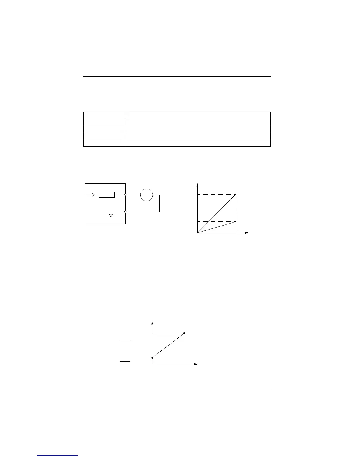
Frequency Meter or Ammeter Calibration (n053, Terminal AM Gain)
This function is used to adjust the analog monitor output signal level.
Parameter n053 determines the slope of the signal output on terminal AM
for the variable being monitored. Increasing this value increases the slope.
Refer to Figure 28.
Frequency Signal Adjustment
When the frequency reference is given by an analog signal at control cir-
cuit terminals FV and FI, the relation between analog voltage (or current)
and frequency reference can be set.
Setting Analog Monitor Output Selection
Output Freq Output frequency (10V/max. frequency) - factory default
Output Amps Output current (10V/inverter rated current)
Output kWatts Output power (10V/inverter rated power)
DC Bus Voltage DC bus voltage [10V/400VDC (230V class), 10V/800VDC (460V class)]
Frequency Meter/Ammeter
(3V 1mA full-scale)
n053
AM
AC
FM
+
-
10V
Analog
Output
0 100%
Monitor Variable
Figure 28 Frequency Meter/Ammeter Calibration
n
0
5
3
=
1
.
0
n
0
5
3
=
0
.
3
3V
( ) indicates when current
reference input is selected.
Frequency Reference
Max. Output Frequency
0V
10V
(4mA)
(20mA)
Gain
100
×
Max. Output Frequency
Bias
100
×
Figure 29 Frequency Signal Adjustment
Chapter 3 - Programming Features
FP5/GP5 Operation
efesotomasyon.com - Control Techniques,emerson,saftronics -ac drive-servo motor