34 FP5/GP5 User’s Manual
Operation by Control Circuit Terminal Signal
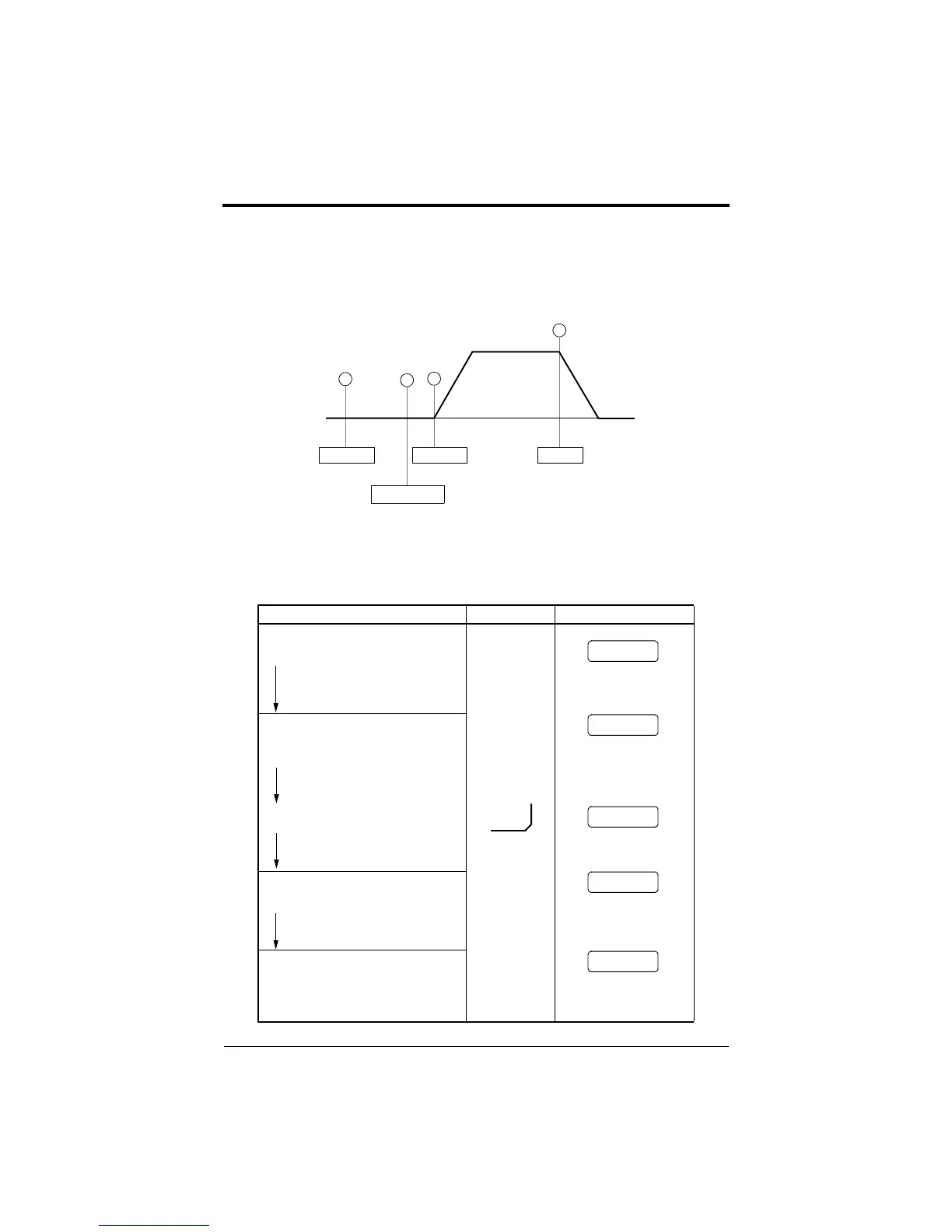
The diagram below shows a typical operation pattern using the control
circuit terminal signals.
Typical Operation Example by Control Circuit Terminal Signal
Description Key Sequence Digital Operator Display
(1)Power ON
·Displays frequency reference value.
REMOTE mode is preset at the factory.
(2)Frequency Setting
·Input frequency reference voltage (current)
by control circuit terminal FV or FI and ver-
ify the input value by the digital operator.
(3)Forward Run
·Close between control circuit terminals S1
and SC to perform forward run.
(4)Stop
·Open between control circuit terminals S1
and SC to stop operation.
Figure 16 Operation Sequence by Control Circuit Terminal Signal
Power ON
Frequency Setting
Operation
Forward
60Hz
Stop
1
2
3
4
DSPL
REMOTE LED (SEQ, REF) ON
For reference voltage 10V
RUN LED ON
STOP LED ON
(RUN LED blinking
during deceleration)
0.0 Hz
Frequency Ref
60.0 Hz
Frequency Ref
0.0 Hz
Output Freq
60.0 Hz
Output Freq
0.0 Hz
Output Freq
· Write-in set value.
Output Frequency Display
Chapter 2 - Operation
Trial Operation
efesotomasyon.com - Control Techniques,emerson,saftronics -ac drive-servo motor