22
Sage Digital ENDEC Manual Rev 2.0
FRONT
Digital
Audio Lock
Incoming
Outgoing
Automatic
Attention
Tone
Sag
e Al
ert
ing
Sy
stem
s,
Inc
.
JP
1
Rev A
.6
C
o
py
ri
g
ht
(c
)
2
00
8
Option
Enter
Alert Alert
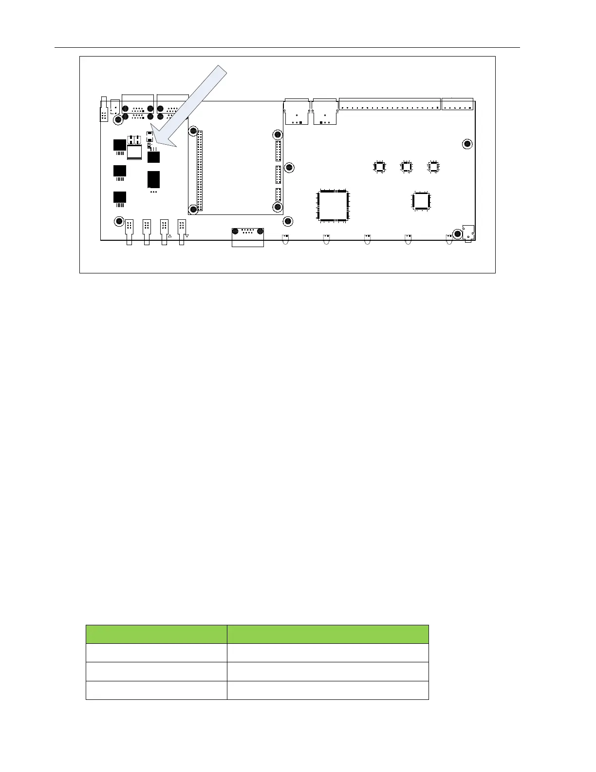
Accessory Power Jumper
(
JP
1
)
Do not source more than 150ma from the accessory power pin 0r 300ma total from any combination of
Com ports. If you are using more than 2 hand-held remote controls, then power the third and fourth remotes
from a 9V power cube.
14.4.1 Enabling ACC Power Pins
The factory default is no power on the ACC PWR pins. To enable these pins, place a jumper on JP1 on the
main board. To do so:
1. Power off the ENDEC.
2. Remove the 6 top cover screws.
3. Slide the cover toward the rear of the ENDEC.
4. Notice JP1 on the large green circuit board covering the bottom of the case. This is the main circuit
board. There is a jumper on one pin of JP1. Do not user JP1 on the red daughter card,
5. Remove the jumper and reinsert it so that the jumper covers both pins.
6. Replace the cover.
14.5 Public Safety: Connecting a Microphone
The microphone connector on the front panel is intended for public safety applications. Broadcasters
typically use the high level Enc In input on the back panel.
The microphone input is amplified; the gain is controlled by MENU.LEVELS.MIC. The microphone input
is designed for use with a low impedance (-200 ohms) dynamic microphone providing at least 20 mV into a
1K load at 100 microbars sound pressure (e.g. Shure 527B or equal).
ENDEC MIC connector pin Signal name
Tip Audio In
Ring PTT
Sleeve Ground