EN | 29SMARTY v2023.2
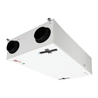
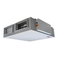
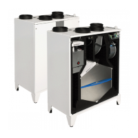
Figure 6.8.4. Smarty 3/4X P S300
SMARTY XV (version 1.1 / 1.2):
• Unscrew the front bolt securing the control board holder to the unit casing.
• Withdraw the automation through the front part.
• Disconnect the connectors from the control board.
• The connectors are marked according to connection location. Thus during automation reassembly please observe the marking of the connection
location of connectors and controller. If the marking on the controller terminals is not visible follow the PCB information provided in "MCB_
MINIMCB TECHNICAL MANUAL".
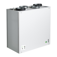
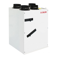
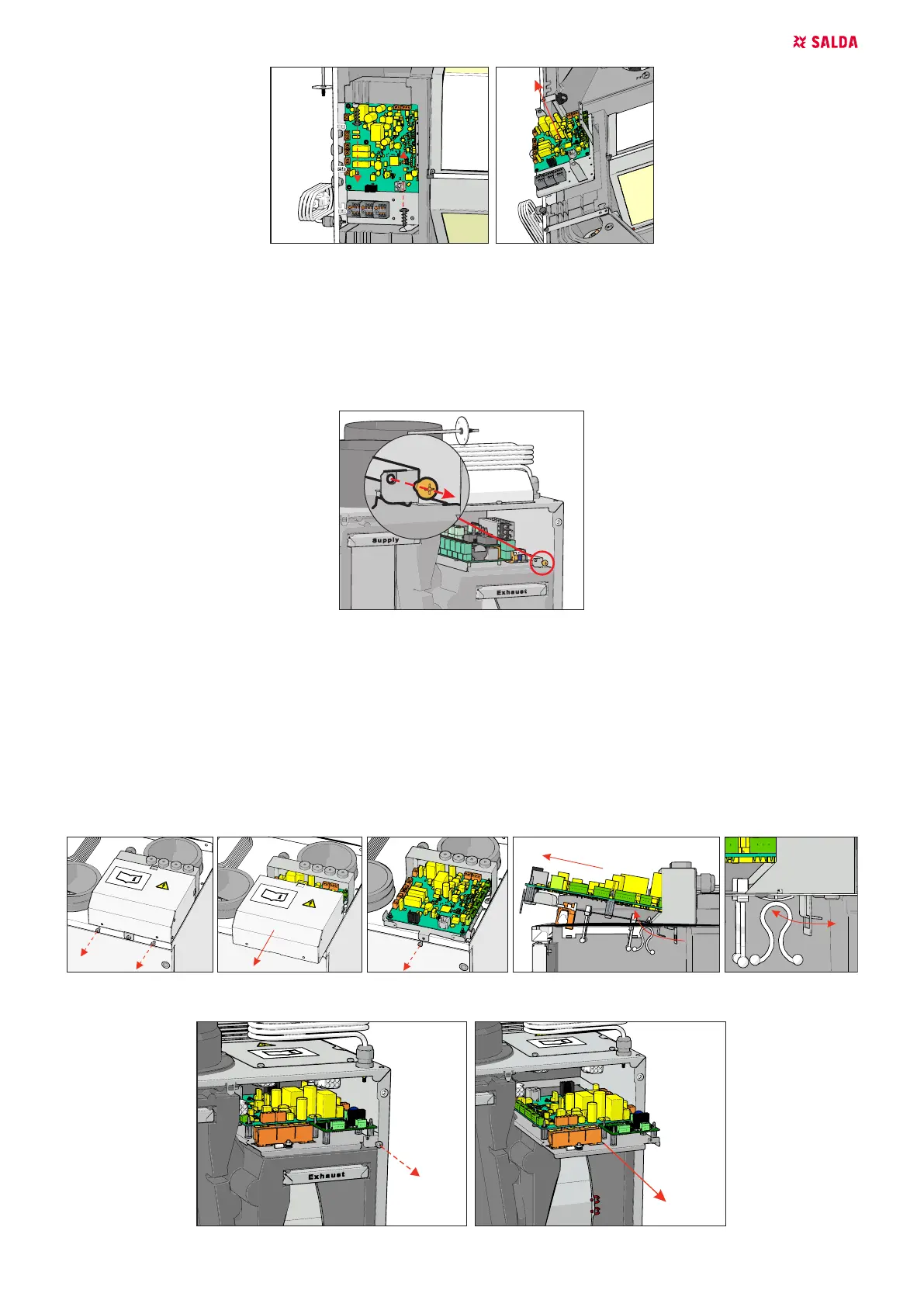
Figure 6.8.5. Smarty 2/3/4X V 1.1/1.2
SMARTY XV (version S300):
To remove control board follow these steps:
• Unscrew control board cover and mounting bolt(s).
• Remove control board cover.
• Disconnect control board's wire connectors from the rest of the unit's wire connectors.
• Remove control board.
Power supply cable for AHUs with S300 is connected permanently and needs to be cut of from the power distribution terminals and re-crimped
with PKC sleeves when reconnecting.
To reassemble follow steps in reverse order. When reconnecting connectors make sure to match each male connector with corresponding female
connector.
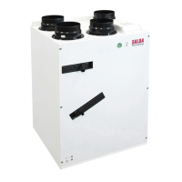
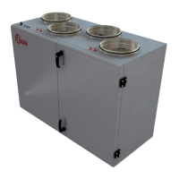
Figure 6.8.6. Smarty 2X V S300 control board
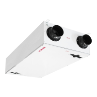
Figure 6.8.7. Smarty 3/4X V S300
 Loading...