EN | 41SMARTY v2023.2
Page
Page
Project template with identification structure in accordance with IEC standard: Page structure with higher-level function and mounting location
Ed.
1
Original
IEC_tpl001
EPLAN
mindaugasbeleckas +
Date
Date
Replaced by
Dampers
1
Modification
0 76
Appr.
Replacement of
8 93
2
4
2022-01-17
EPLAN Software & Service
GmbH & Co. KG
2
2
=
Name
5
2/
1
2
Outside air damper control signal (L, 230V)
Output digital relay 24-230 V AC, max 6.3A, normally open/closed
Q34
Ref
D1
GND
+24VDC
Smoke
detector
T3
T7
3 124
Operation indication output signal (L, 230V)
Output digital relays 24-230 V AC, max 6.3A,
normally open/closed
Q24
Connected by user
213
T19
1
2
Alarm indication output signal (L, 230V)
Output triac, 230V AC, max. 10A (<1s),
nominal current: 0,05-1A.
Y1
12
KNX+
KNX-
T14
KNX PL-Link, galvanic
isolation, 40mA rated
T15
To air quality sensor
or remote controller
Ref
D2
GND
+24VDC
NO/NC switch
T3
213
T12
Modbus slave port1 over
RS485, HMI/RU interface
RS485 A+
RS485 B-
RS485 Ref
12
3
Modbus RTU
Figure 8.11.1. D2 digital input connection
After connection, conguration has to be performed. For more information see section "ACCESSORIES SETUP (VERSION S300)".
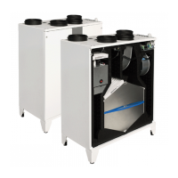
8.12. OPERATION INDICATION OUTPUT (VERSION S300)
If indication about the status of the air handling unit is needed, it can be connected to dedicated Q24 signal on T7:1. When AHU is ON, indication
output will provide voltage for indicating device.
After connection, conguration has to be performed. For more information see section "ACCESSORIES SETUP (VERSION S300)".
Page
Page
Project template with identification structure in accordance with IEC standard: Page structure with higher-level function and mounting location
Ed.
1
Original
IEC_tpl001
EPLAN
mindaugasbeleckas +
Date
Date
Replaced by
Dampers
1
Modification
0 76
Appr.
Replacement of
8 93
2
4
2022-01-17
EPLAN Software & Service
GmbH & Co. KG
2
2
=
Name
5
2/
1
2
Outside air damper control signal (L, 230V)
Output digital relay 24-230 V AC, max 6.3A, normally open/closed
Q34
Ref
D1
GND
+24VDC
Smoke
detector
T3
T7
3 124
Operation indication output signal (L, 230V)
Output digital relays 24-230 V AC, max 6.3A,
normally open/closed
Q24
Connected by user
213
T19
1
2
Alarm indication output signal (L, 230V)
Output triac, 230V AC, max. 10A (<1s),
nominal current: 0,05-1A.
Y1
12
KNX+
KNX-
T14
KNX PL-Link, galvanic
isolation, 40mA rated
T15
To air quality sensor
or remote controller
Ref
D2
GND
+24VDC
NO/NC switch
T3
Connected by user
213
T12
Modbus slave port1 over
RS485, HMI/RU interface
RS485 A+
RS485 B-
RS485 Ref
12
3
Modbus RTU
Figure 8.12.1. Operation indication output connection
WARNING: High voltage on output.
8.13. ALARM INDICATION OUTPUT (VERSION S300)
In the same way as operation indication, alarm indication signal can be provided by the control board. Indicator has to be connected to Y1 output
on T19:1.
Page
Page
Project template with identification structure in accordance with IEC standard: Page structure with higher-level function and mounting location
Ed.
1
Original
IEC_tpl001
EPLAN
mindaugasbeleckas +
Date
Date
Replaced by
Dampers
1
Modification
0 76
Appr.
Replacement of
8 93
2
4
2022-01-17
EPLAN Software & Service
GmbH & Co. KG
2
2
=
Name
5
2/
1
2
Outside air damper control signal (L, 230V)
Output digital relay 24-230 V AC, max 6.3A, normally open/closed
Q34
Ref
D1
GND
+24VDC
Smoke
detector
T3
T7
3 124
Operation indication output signal (L, 230V)
Output digital relays 24-230 V AC, max 6.3A,
normally open/closed
Q24
Connected by user
213
T19
1
2
Alarm indication output signal (L, 230V)
Output triac, 230V AC, max. 10A (<1s),
nominal current: 0,05-1A.
Y1
12
KNX+
KNX-
T14
KNX PL-Link, galvanic
isolation, 40mA rated
T15
To air quality sensor
or remote controller
Ref
D2
GND
+24VDC
NO/NC switch
T3
Connected by user
213
T12
Modbus slave port1 over
RS485, HMI/RU interface
RS485 A+
RS485 B-
RS485 Ref
12
3
Modbus RTU
Figure 8.13.1. Alarm indication output connection
WARNING: High voltage on output.
NOTE: lower than 0,05A loads can operate incorrectly.
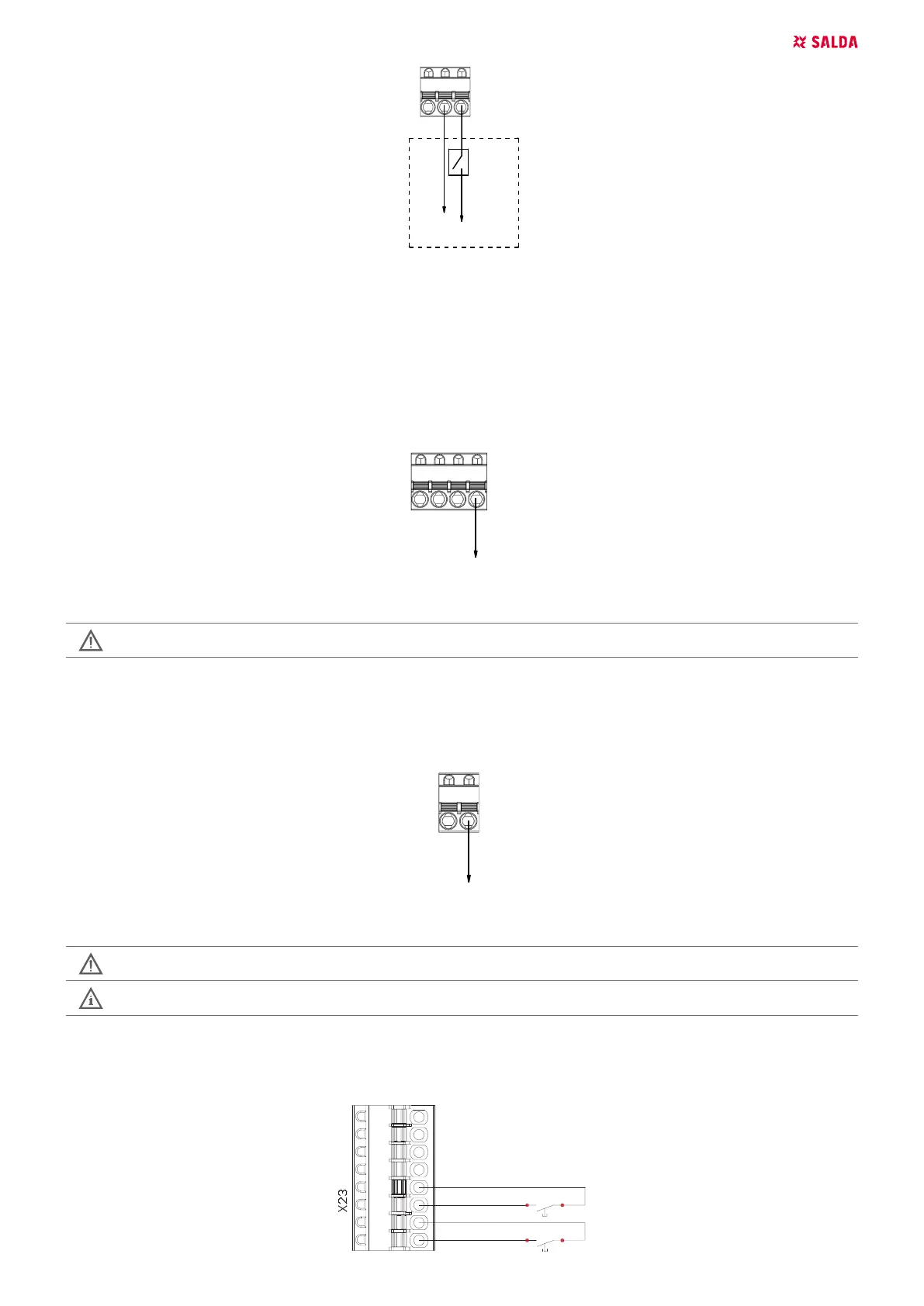
8.14. FIRE PLACE PROTECTION (VERSION 1.1)
Wiring diagram.
Automation controller C zone, X23 connector.
1234 5678
-Fire Place II
DI4
+12VDC
+12VDC
DI3
-Fire Place I
 Loading...