36 | EN SMARTY v2023.2
KE
Mini MCB
TJ
EKA
TJ
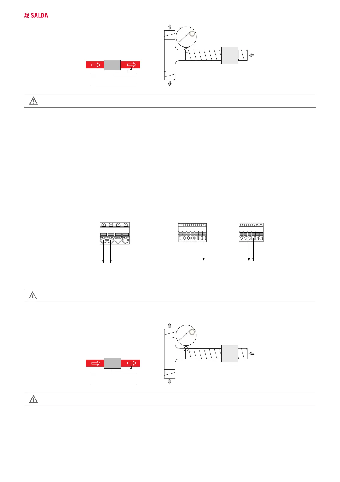
When using the supply air heater, the supply air sensor (TJ) must be installed downstream the heater (or cooler) at the length
of sensor cable allows or up to the rst branching or bend of air transportation system.
Only heaters with up to 0.6 kW power circuit can be connected directly to the control board. The heaters of higher power heaters must be con-
nected to separate electric power circuit.
8.1.3. VERSION S300
SMARTY air handling units are able to control one heater or preheater coil at a time. When the preheater is used, one more temperature sensor
has to be installed to the system. After connection, conguration has to be performed. For more information see section "ACCESSORIES SETUP
(VERSION S300)".
8.1.3.1. HEATER
In order to use a heating coil, following signals are required to be connected to the control board:
1. Electric heating coil command;
2. Heating coil overtemperature detector;
3. Heating coil position signal.
Page
Page
Project template with identification structure in accordance with IEC standard: Page structure with higher-level function and mounting location
Ed.
Original
IEC_tpl001
EPLAN
justasbalsys +
Date
Date
Replaced by
Heater/preheater
1
Modification
0 76
Appr.
Replacement of
8 93
2
2
4
2022-01-13
EPLAN Software & Service
GmbH & Co. KG
1
2
=
Name
5
1/
T7
3124
Electric heating coil command
Output digital relays 24-230 V AC, max 6.3A, normal
ly open/closed
1234567
Heating coil overtemperature detector
T1
T18
Heating coil position
Input Digital/NTC10k
(in reference to GND) Output 0-10V
A3X8
123456
GND
Q13
Q14
T7
3124
Electric preheating coil command
Output digital relays 24-230 V AC, max 6.3A, normally open/closed
1234567
Air temperature sensor after preheating coil
T1
T18
Preheating coil position
Input Digital/NTC10k
(in reference to GND) Output 0-10V
A3
X8
123456
GND
Q13 Q14
Preheating coil overtemperature detector
X3
Input Digital/NTC10k
(in reference to GND)
12345678
T2
Heater
Preheater
1234567
Outside air temperature sensor
T1
Input Digital/NTC10k
(in reference to GND)
B1
Figure 8.1.3.1.1. Signals for electrical heater
NOTE: Power supply for the heater is not shown.
Heater Installation Diagram
Electric heater must be installed inside the air duct. The layout is based on airow direction ELECTRIC HEATER > SUPPLY AIR SENSOR (TJ).
KE
Mini MCB
TJ
Siemens S300
1
KE1
TJ
When using the supply air heater, the supply air sensor (TJ) must be installed downstream the heater (or cooler) at the length
of sensor cable allows or up to the rst branching or bend of air transportation system.
8.1.3.2. PREHEATER
In order to use a preheating coil, following signals are required to be connected to the control board:
1. Electric preheating coil command;
2. Air temperature after preheating coil;
3. Preheating coil overtemperature detector;
4. Preheating coil position signal.
 Loading...