14
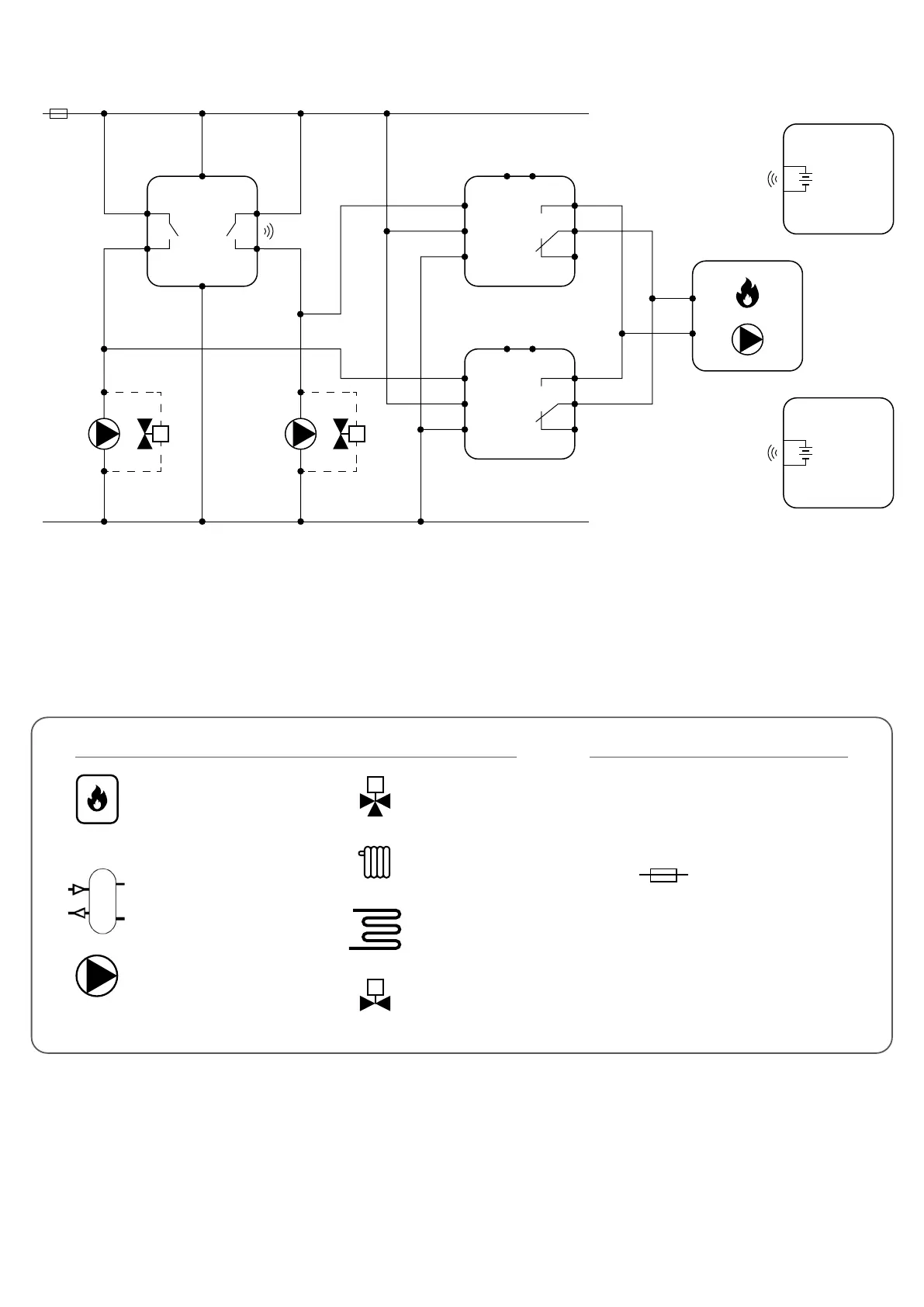
Electric diagram:
L, N - power supply 230V
NO, COM - voltage-free output
- fuse
Legend:
Symbols explanation:
Buer / Coupler
Thermostatic
mixing valve
Radiator heating
Underoor heating
Shut-o valve
Pump
Boiler - Boiler connection*
- Boiler’s contacts for ON/OFF
thermostat (according to the
boiler’s instructions)
T
* Relays RM-16A No. 1 and No. 2 are used only when we want to control the boiler (ON / OFF). Then connect the relay output contacts to the boiler in the
place intended for connecting the room thermostat.
M
M2M1
L
AC 230V
P1 P2
N
COMCOM
NONO
iT500RX
N
L
iT300
3V
2 x AAA
iT500TX
3V
2 x AA
(input)
(input)
RM-16A
NO
NO
COM
COM
NC
SL
N
L
(output)
(input)
(output)
(input)
RM-16A
NO
NO
COM
COM
NC
SL
N
L
M M
CH
OUTPUT
AUX
OUTPUT