34 | SAMLEX AMERICA INC.
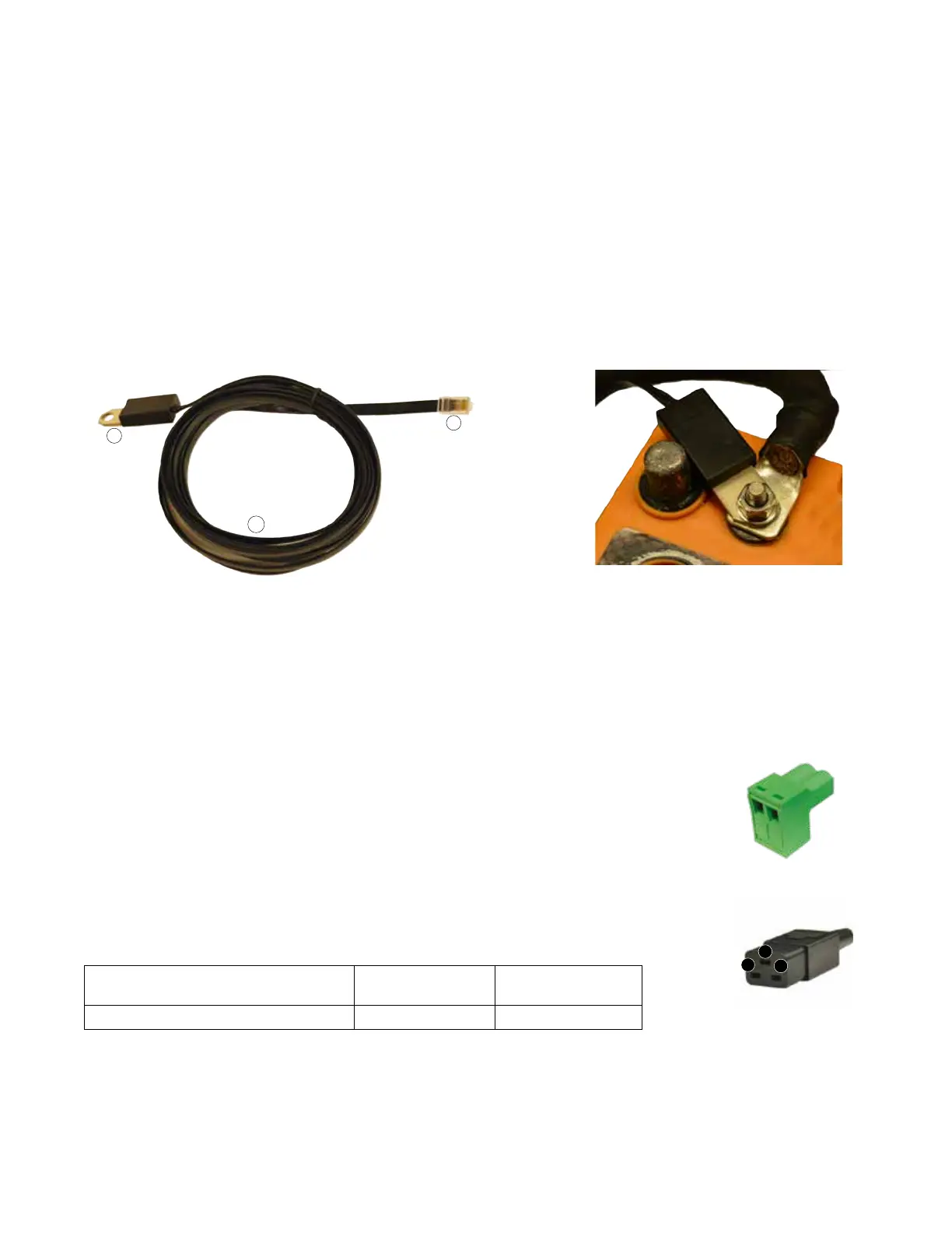
2.5 BATTERY TEMPERATURE SENSOR EVO-BCTS [FIG 2.5(a)]
Temperature Sensor [Negative Temperature Coefcient (NTC) resistor]: Mounting hole: 10mm/0.39” suitable for 3/8”
or 5/16” battery studs
1. RJ-45 Plug: Pins 1 to 4 Ò + NTC ; Pins 5 to 8 Ò – NTC (See pinout of mating RJ-45 Jack at 19, Fig 2.1)
2. 5 meter/16.5 ft cable
Note: Mount the sensor on the Positive or Negative terminal stud on the battery as shown in Fig 2.5(b)
Fig 2.5(a) Temperature Sensor Model EVO-BCTS Fig 2.5(b) Temperature Sensor Installation
LEGEND for Fig. 2.5(a)
1. Temperature Sensor with Ring Terminal: Mounting hole: 10mm/0.39” suitable for 3/8” or 5/16” battery studs
2. RJ-45 Plug: Plug this into the RJ-45 Jack marked "Battery Temp. Sensor" (6, Fig 2.1). See pinout of mating
RJ-45 at Fig 3.13.
3. 5 meter/16.5 ft cable
2.6 CONTENTS OF PACKAGE
• Inverter/Charger
• Temperature Sensor EVO-BCTS [Fig 2.5(a)]
• DC Terminal Covers (1a, 1b: Fig 2.1) (Fitted on the unit with 2 screws each)
• Mating Connector for Remote On/Off Control* (16: Fig 2.1)
• IEC 60320 C-19, Socket Connector**[Mating connector for male AC Power
Inlet Plug (9, Fig 2.1)
• Wire End Terminals for AC Wiring (Fig 3.11) for EVO-1212F-HW/ EVO-1224-HW
Model AWG#12
(for input wiring)
AWG #14
(for output wiring)
EVO-1212F-HW and EVO-2224-HW 4 4
• Owner's Manual
• Quick Start Guide
SECTION 2 | Components & Layout
Mating Connector for On/ Off
Control (16 Fig 2.1)
IEC 60320, C-19 Socket
Connector (14 Fig 2.1)
G
N
L
**
*