28 EB 8394 EN
Mounting and start-up
5.2 Direct attachment
5.2.1 Type 3277-5 and
Type2780-2 Actuators
Î Required mounting parts and accesso-
ries: Table2 on page16.
Î Observe travel tables on page20.
Actuator with 120cm² diaphragm area
Depending on the type of positioner attach-
ment, the signal pressure is routed either left
or right of the yoke through a hole to the ac-
tuator diaphragm.
Î Depending on the fail-safe action of the
actuator "actuator stem extends" or "ac-
tuator stem retracts", rst attach the swi-
tchover plate (9) to the actuator yoke
(while aligning it with the corresponding
symbol for left or right attachment ac-
cording to the marking, see Fig.6).
1. Mount connecting plate (6) or pressure
gauge bracket (7) with pressure gauges
on the positioner, making sure the two
seals (6.1) are seated properly.
2. Screw the screw plug (4) on the back of
the positioner into the hole below it (park
position) (see Fig.8) and seal the signal
pressure output on the connecting plate
(6) or on the pressure gauge bracket (7)
with the stopper (5) included in the ac-
cessories.
3. Place follower clamp (3) on the actuator
stem, align it and screw tight so that the
mounting screw is located in the groove
of the actuator stem.
4. 15 mm travel: Keep the follower pin (2)
on the M lever (1) on the back of the po-
sitioner in the pin position 35 (delivered
state). 7.5 mm travel: Remove the fol-
lower pin (2) from the pin position 35,
reposition it in the hole for pin position
25 and screw tight.
5. Insert formed seal (15) into the groove of
the positioner housing.
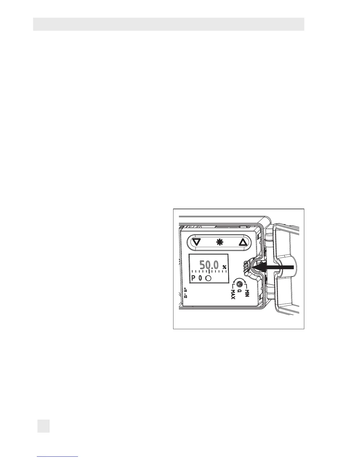
6. Place positioner on the actuator in such a
manner that the follower pin (2) rests on
top of the follower clamp (3). While do-
ing this, press on the ribbed area shown
in Fig.5 to lock the pick-up lever in the
top position. The lever (1) must rest on
the follower clamp with spring force.
Fig.5: Locking the pick-up lever in position
7. Mount the positioner on the actuator us-
ing the two xing screws.