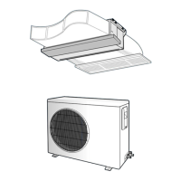
Connecting the Indoor Unit Assembly Piping
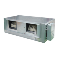
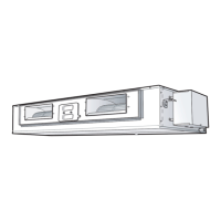
Indoor unit
Outdoor unit
Oil trap (Must be instal-
levery 10m)
a. When the indoor unit is above the outdoor unit
b. When the outdoor unit is above the indoor unit
Radius
5cm
Oil trap(suction
tube)
Outdoor unit
Indoor unit
Oil trap(Must be install-
edevery 10m)
Liquid refriger-
ant port
Drain hose
connection
port
Gas
refrig-
erant
port
There are two refrigerant pipes of differing diameters:
◆ A smaller one for the liquid refrigerant
◆ A larger one for the gas refrigerant
◆ The thickness of tube should not less than 1.0mm
◆ The inside of copper tube must be clean & has no dust.
The connection procedure for the refrigerant pipes varies according to
the exit position of the pipes from the indoor unit, as seen when facing
the indoor in the “A” side.
◆ Liquid refrigerant port
◆ Gas refrigerant port
◆ Drain hose connection port
1
Remove the pinch pipe on the pipes and connect the assembly pipes
to each pipe, tightening the nuts, first manually and then with a torque
wrench, a spanner applying the following torque.
Outer Diameter Torque (kgf•cm)
6.35 mm (1/4") 140~170 kgf
•cm
9.52 mm (3/8") 250~280kgf
•cm
12.70 mm (1/2") 380~420kgf
•cm
15.88 mm (5/8") 440~480kgf
•cm
19.05 mm (3/4") 990~1210kgf
•cm
22.23 mm (7/8") 990~1210kgf
•cm
◆ If the pipes must be shortened refer to page 16.
Note
2
Must use insulator which is thick enough to cover the refrigerant tube to
protect the condensate water on the outside of pipe falling onto the floor
and the efficiency of the unit will be better.
3
Cut off any excess foam insulation.
4
Be sure that there must be no crack or wave on the bended area.
5
It would be necessary to double the insulation thickness (10mm or
more) to prevent condensation even on the insulator when if the
installed area is warm and humid.
6
Shape an oil trap as shown in figure the oil trap must be formed every
level difference of 10m.
 Loading...