16
INSTALLATION
CAUTION
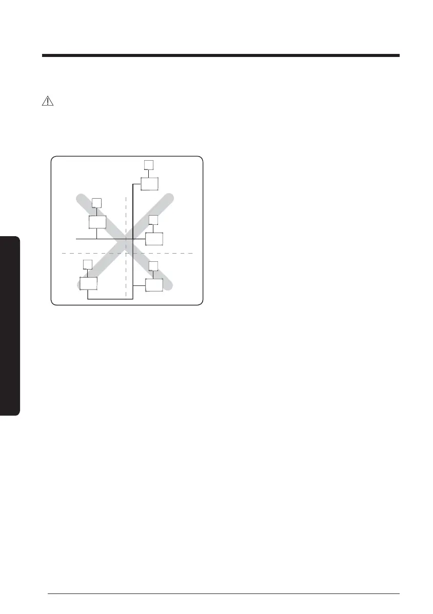
• The circuit diagram on the cables as shown above represents only outline and it does
not describe detailed instruction on the actual installation work.
• The communication cable should not branch due to possible communication error.
Wired remote controller
FCU KIT
F1, F2
• When peeling off outer sheath of the power cable, be careful not to damage the inner
sheath of the cable by using a correct tool.
• The unpeeled sheath of the power and communication cable must be inserted more than
20 mm(0.78 inch) to inside of FCU KIT holder.
• The installation of communication cable should be separated from power cable or other
communication cables.
FCU KIT installation