9
CHECKING BEFORE THE INSTALLATION
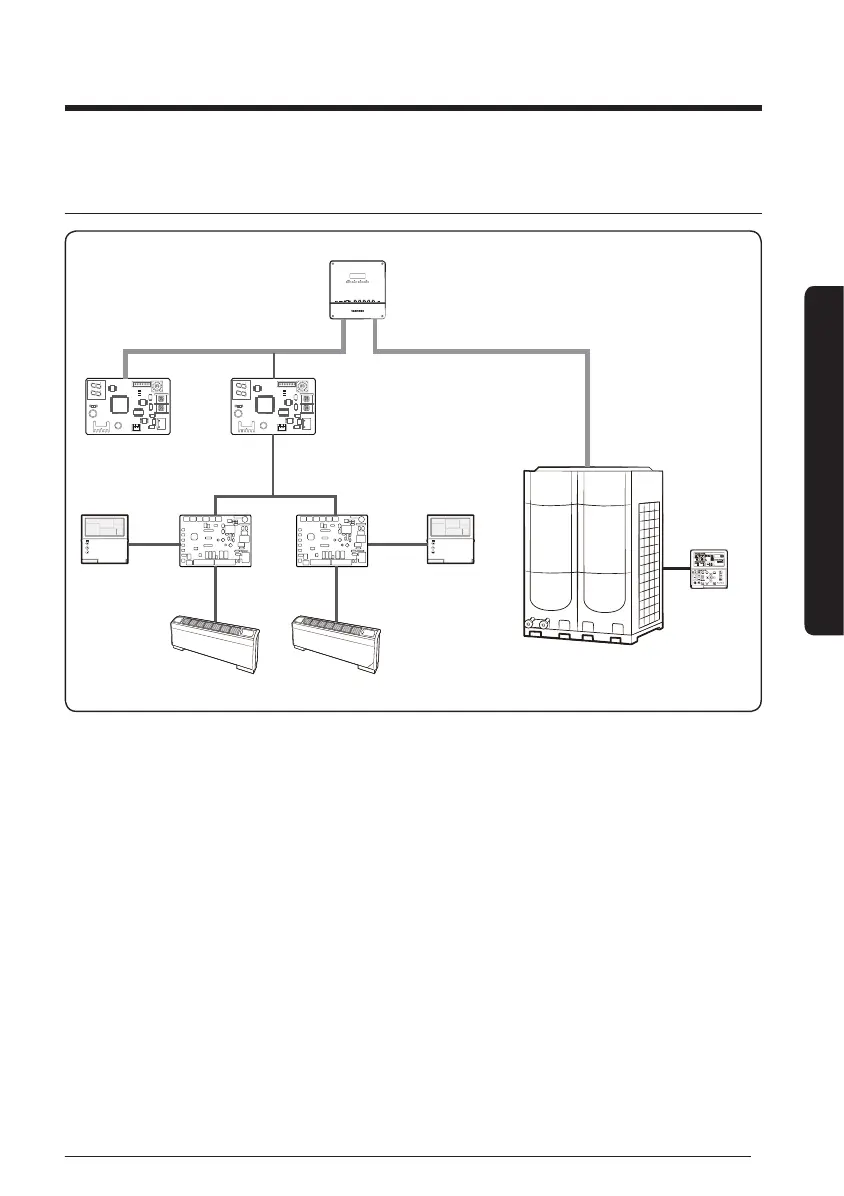
Diagram of DMS 2.5 and DVM CHILLER & FCU
CN4
CN3
RED
CN2
BLK
YEL
RED
Y-GRN
CN4
CN3
RED
CN2
BLK
YEL
RED
Y-GRN
DMS2.5 (MIM-D01AN)
Connect up to 16 FCU interface modules
R1,R2
Module
controller
(MCM-A00N)
Wired remote
controller
F3,F4
F3,F4
F1,F2
FCU KIT
(MIM-F00N)
FCU
FCU
Connect up to 16 FCU KITs
DVM CHILLER
y
FCU KIT and FCU interface module is for integrated control of FCU with DVM CHILLER by
DMS 2.5.
y
Maximum number of FCU interface modules that can be installed to a DMS2.5, and
maximum number of FCU KITs that can be installed to a FCU interface module is both 16.
y
Maximum number of FCU interface modules that can be installed to a channel of DMS2.5
is 16 (Max. 128 FCU KITs).
y
Some functions of wired remote controller may not work. (Refer to page 47.)
y
Control logic of DMS2.5 should be set to interlock FCU KIT and DVM CHILLER. Refer to
user manual of DMS2.5 for setting control logic.