21
INSTALLATION
WARNING
y
Be sure to use the conduits and conduit ttings when extracting the wires for safety.
NOTE
• Arrange communication cables (F1, F2, R1, R2) to the opposite way of power cable.
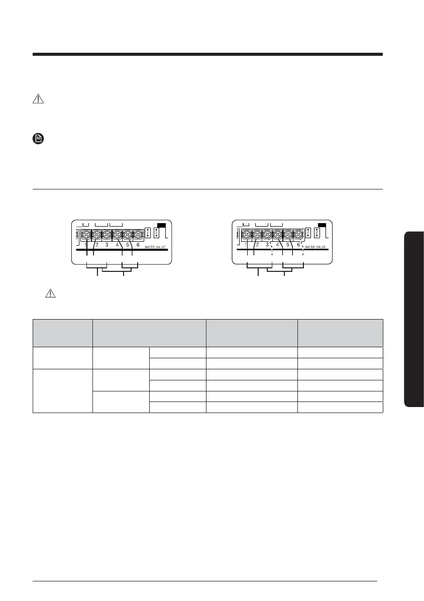
Diagram of ASS'Y control
1 Water valve contact output status for operation mode.
Pipe type Operation power output
AC power output
(Max. 0.5 A)
Remarks
2-pipe
Cooling/
Heating
Thermo ON 1-2 Normal Close Type
Thermo OFF 1-3 Normal Open Type
4-pipe
Cooling
Thermo ON 1-2 Normal Close Type
Thermo OFF 1-3 Normal Open Type
Heating
Thermo ON 4-5 Normal Close Type
Thermo OFF 4-6 Normal Open Type
y
Connect 3 Way valve power cable according to value of operation mode power output.
y
Select each valve that is below 0.5 A of operation current.
y
Installation option setting(05series, SEG14) is required to dene 2 pipe or 4 pipe system.
CAUTION
y
When connecting the valve power cable, be sure to connect the wires (N, L) to the correct terminals (N, L).
- Failure to do so may damage the PBA.
NNLLLL
When using a 2-way valve (normal close type) When using a 3-way valve
NNLLLL
Terminals for 2-pipe type Terminals for 4-pipe type Terminals for 2-pipe type Terminals for 4-pipe type