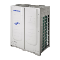
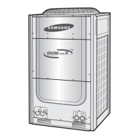
Do you have a question about the Samsung DVM Plus 2 Series and is the answer not in the manual?
The following safety precautions must be taken when installing the unit.
If you don't follow the safety precautions, you may get the risk of serious wound or death.
If you don't follow the safety precautions, you may get the risk of injury or loss of property.
Guides on detecting and resolving system errors using LED displays and checking causes.
Wiring diagrams for various indoor unit types: 1-way, 2-way, 4-way, mini 4-way, duct, and wall-mounted.
Wiring diagrams for outdoor units, covering different phases and horsepower ratings.
Diagrams showing refrigerant flow during cooling for different outdoor unit models.
Diagrams illustrating refrigerant flow during heating operation for various outdoor unit models.
Provides flowcharts to guide troubleshooting for outdoor unit operation issues.
Explains how to perform initial tracking and check communication errors indicated on the display.
Details troubleshooting steps for reverse phase or missing phase detection errors in 3-phase power systems.
Describes how to interpret LED lamp displays for indoor unit self-diagnosis of various errors.
Provides a guide to understanding outdoor unit error codes, their meanings, and troubleshooting steps.
| Refrigerant | R410A |
|---|---|
| Heating Capacity | 8.0 - 24.0 kW |
| Indoor Unit Options | Ceiling Cassette, Ceiling Concealed |
| Control System | Centralized Control |
| Indoor Unit Dimensions (WxHxD) | Varies by model |
| Outdoor Unit Dimensions (WxHxD) | Varies by model |
| Indoor Unit Weight | Varies by model |
| Outdoor Unit Weight | Varies by model |
| Type | VRF (Variable Refrigerant Flow) |


 Loading...