EasyManuals Logo

Samsung DVM Plus 2 Series User Manual

Samsung DVM Plus 2 Series
522 pages
To Next Page IconTo Next Page
To Previous Page IconTo Previous Page
Page #379 background imageLoading...
Page #379 background image
Samsung Electronics10-23
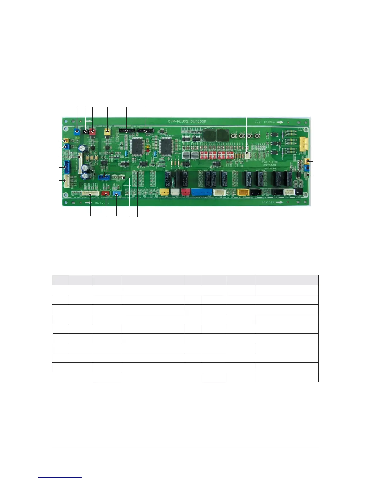
PCB Diagram
10-3-2 MAIN PCB_DC
1 523
*
(
)
! @ # $ % ^ &
4
No. CN# COLOR FUNCTION
!
CN12 BLUE 12V SUPPLY
@
CN13 BLACK 5V SUPPLY
#
CN31 RED INDOOR COMM
$
CN32 YELLOW OUTDOOR COMM
%
CN92 BLACK SUB MICOM DOWN
^
CN91 BLACK MAIN MICOM DOWN
&
OPT1 WHITE CO/HP SELECT
*
CN51 YELLOW COMP1 CT INPUT
(
CN52 BLUE COMP2 CT INPUT
)
CN53 RED COMP3 CT INPUT
No. CN# COLOR FUNCTION
1
CN41 BLUE LOW SENSOR
2
CN12 RED HIGH SENSOR
3
CN44 WHITE COMP/SUCTION SENSOR
4
CN64 BLUE LIQUID EEV
5
CN63 YELLOW EEV2
6
CN47 WHITE OIL/2TUBE/COND SENSOR
7
CN62 BLUE EEV
8
CN49 BLUE OUTAIR SENSOR
9
CN45 YELLOW SUMP SENSOR
0
CN99 WHITE DC SIGNAL TO POWER PCB
9
8
0
7
6

Table of Contents

Questions and Answers:

Question and Answer IconNeed help?

Do you have a question about the Samsung DVM Plus 2 Series and is the answer not in the manual?

Samsung DVM Plus 2 Series Specifications

General IconGeneral
BrandSamsung
ModelDVM Plus 2 Series
CategoryAir Conditioner
LanguageEnglish

Related product manuals