20
INSTALLATION
y
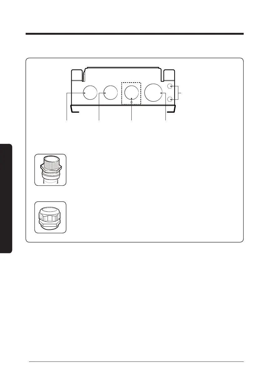
Power cable: Conduit and Conduit tting (1/2") work by installer
y
Water valve: Conduit and Conduit tting (1/2") after separating
screw by installer when necessary
y
DC, zero voltage contact: cable gland (3/4") work by installer
DC Communication cable (F1, F2, R1, R2),
Room sensor (optional), Water sensor,
Wired remote controller, External contact
AC, water valve
power output cable
(BLDC Fan Control,
Modulating Valve 1,2)
AC, FAN power
output cable
AC, Power
input cable
Spare holes
(Use for DC cables)
y
Use conduit (1/2") and tting (1/2") for power cable, and use cable gland (3/4") for DC
cables.
y
Each parts must be certied by national authority.
– USA: UL certied products (UL514B), Europe: CE certied products
y
Withdraw DC cables by spare holes if the DC cable wire holder is too tight.
y
Use double-sheathed cables when using DC spare holes.
y
Fix the power and communication cable at internal mount tie by using cable ties.
y
Do not unscrew water valve cable wire holder if not used.
y
Installation may be more simple by inserting sensor connector before connecting
communication cable.
y
The Water Valve and Modulating Valve cannot be used at the same time.
FCU KIT installation