23
INSTALLATION
Pipe type Location of Sensor Connector Location of pipe
2-pipe Water-IN 1 Water inlet pipe
4-pipe
Water-IN 1 Chilled water inlet pipe
Water-IN 2 Heating water inlet pipe
y
When using 4-pipe system, set SEG14 of 05 series installation option as 1.
y
In case of opposite installation of water pipe 1, 2 sensor in 4 pipe system, error(pipe
block) will be occurred in 30minutes of operation(E992 or E993).
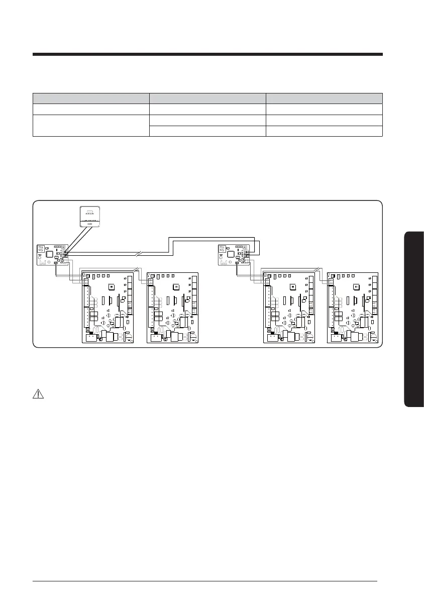
3 FCU interface module connection
CN4
CN3
RED
CN2
BLK
YEL
RED
Y-GRN
CN4
CN3
RED
CN2
BLK
YEL
RED
Y-GRN
V1
V2
F1
F2
DMS(2.5 or later)/BACnet/LonWorks
Connect up to 16 FCU KITs
Connect up to 16 FCU interface
modules
R1
R2
y
Maximum number of FCU interface module and FCU KIT that can be installed to a channel
of DMS is 16 and 128.
CAUTION
y
Make sure that the FCU interface module must be installed even though the FCU kit is
installed solely (single or multiple installation) without its upper level controller.