Firmware update
7-6
Copyright© 1995-2012 SAMSUNG. All rights reserved.
준준준
1. SD card less than 1GB
- It is recommended to use a SD card with less than 1GB.
2. Soldering iron
- It is used to short out the TP on MAIN PCB.
3. The latest rmware les such as WB200F_U_SR_SXXXXXX.zip
- You can download the latest rmware le from the K-zone or Samsung website.
- Note that the name of the rmware le may vary depending on WB model.
Required materials
5. LED will turn on blink when turn on the camera. The MAIN PCB recovery process will proceed.
(It will takes about 2 minutes.)
6. LED will turn off when the recovery process is complete.
7. Remove the Soldering.
8. Remove the SD card and then assemble the camera.
- Assemble the MAIN FRAME → LCD → KEY PCB → BACK COVER
9. Turn the power of the camera on again to check whether camera has been functioning.
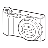
1. Remove the camera as Fig. 7-9.
- Removing the BACK COVER → KEY PCB → LCD → MAIN FRAME.
2. Download the latest rmware le and copy it to the SD card .
- Save the latest version rmware le into root folder in SD card.
(DATAWB200.bin)
- Do not need to save the “fwup.txt” le. Only save the “DATAWB200.bin” le.
3. Insert the memory card containing the rmware data le into the camera.
* You can proceed with the upgrade only when the battery level is full (Icon showing full up to 3rd level).
4. Soldering the TP in red circle on Main PCB to short out the circuit.
Then press the power button to turn on the camera.
7-4 How to recover the MAIN PCB
■
This section describes how to recover the MAIN PCB when camera stops functioning due to power failure or some other reasons
during the rmware process.
■ It is not necessary to go over all the adjustment process again since the existing adjustment data is deleted.
Fig. 7-9
Location soldering

 Loading...