70
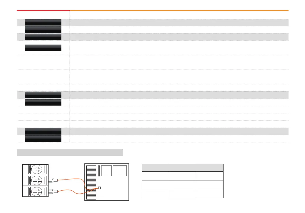
[Table 13-1] Display method for thermocouple
Instruction Description
Set the input sensor type
Set the tag name of the graph recording screen
Input maximum 8 characters using the 0~9, A~Z and special character.
Set the Y/N for the basic contact point compensation for the terminal connected with sensor. Refer to [Table 13-1]
●
Selection of Y/N for using RJC in case of T/C sensor type.
It does not compensate the temperature of terminal and displays the current measured data
[Measured temperature in sensor side - Standard contact point temperature].
The currently measured data displays the temperature measured from sensor side with compensation to the standard
contact point temperature.
Display the standard contact point temperature.
Setting the upper and lower limit of the input sensor. Refer to [Table 13-3]
Set the operation direction of the current data in case of sensor open
Display the unpredictable random data when sensor is open
Display of “+S.Open” while PV increases when sensor is open
Display of “+S.Open” while PV decreases when sensor is open
Set the data measurement method. Refer to [Table 13-2]
Set the number of digit in case of DCV sensor type.
NO
UP
DOWN
T/C
T/C + RJC
RJC
SENSOR TYPE
DISPLAY UNIT
TAG NAME
T/C DISPLAY
SENSOR RANGE
PV WHEN S.OPN
MEASURE METHOD
DOT POSITION
1
2
3
A
b+
B-
SYSTEM
Measuring the
temperature
in sensor side
500℃
Standard contact
point temperature
20℃
Thermocouple
T/C
T/C + RJC
RJC
Measured data
480℃
500℃
20℃
Formula
500-20
(500-20)+20
20