Chapter 4 – SD Card Protocol Description
Revision 2.2 SanDisk SD Card Product Manual
© 2004 SanDisk Corporation 4-41 12/08/04
2) R1b is identical to R1 with the additional busy signal transmitted on the data line.
3) R2 (CID, CSD register): response length 136 bits.
The content of the CID Register is sent as a response to CMD2 and CMD10. The content
of the CSD Register is sent as a response to CMD9. The only bits transferred are [127...1]
of the CID and CSD; the reserved bit (0) in these registers is replaced by the end bit of the
response.
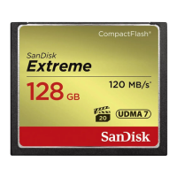
Table 4-20 Response R2
Bit Position
135 134 [133:128] [127:1] 0
Width (bits)
1 1 6 127 1
Value
0 0 111111 x 1
Description
start bit transmission bit reserved CID or CSD register incl.
internal CRC7
end bit
4) R3 (OCR Register): response length 48 bits.
The contents of the OCR Register are sent as a response to CMD1.
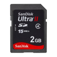
Table 4-21 Response R3
Bit Position
47 46 [45:40] [39:8] [7:1] 0
Width (bits)
1 1 6 32 7 1
Value
0 0 111111 x 111111 1
Description
start bit transmission bit reserved OCR Register reserved end bit
R4 and R5: responses are not supported.
5) R6 (Published RCA response): response length 48 bits. Bits 45:40 indicate the response
command’s index; in that case it will be 000011 (together w/bit 5 in the status bits it means
= CMD3. The 16 MSBs of the argument field are used for the published RCA number.
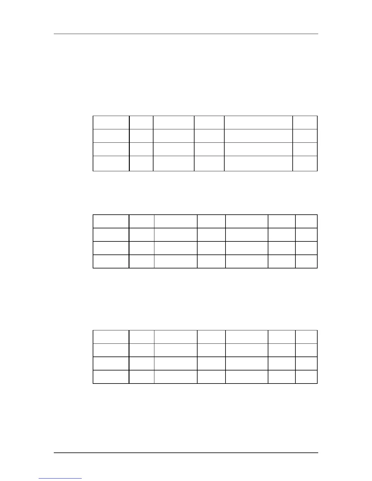
Table 4-22 Response R6
Bit Position
47 46 [45:40] [39:8] [7:1] 0
Width (bits)
1 1 6 32 7 1
Value
0 0 111111 x 111111 1
Description
start bit transmission bit reserved OCR Register reserved end bit
 Loading...