Chapter 3 – SD Card Interface Description
Revision 2.2 SD Card Product Manual
© 2004 SanDisk Corporation 3-3 12/08/04
3.2 SD Bus Topology
The SD Memory Card bus has six communication lines and three supply lines.
• CMD
• DAT0-3
• CLK
• VDD
• VSS[1:2]
The description of each signal is contained in Table 3-3.
Table 3-3 MMC Bus Signal Descriptions
Name Description
CMD Command is a bi-directional signal. Host and card drivers are operating in push-
pull mode.
DAT0-3 Data lines are bi-directional signals. Host and card drivers are operating in push-
pull mode.
CLK Clock is a host to card si
nal. CLK o
erates in
ush-
ull mode.
V
DD
Power su
l
line for all cards.
V
SS
1:2
Two
round lines.
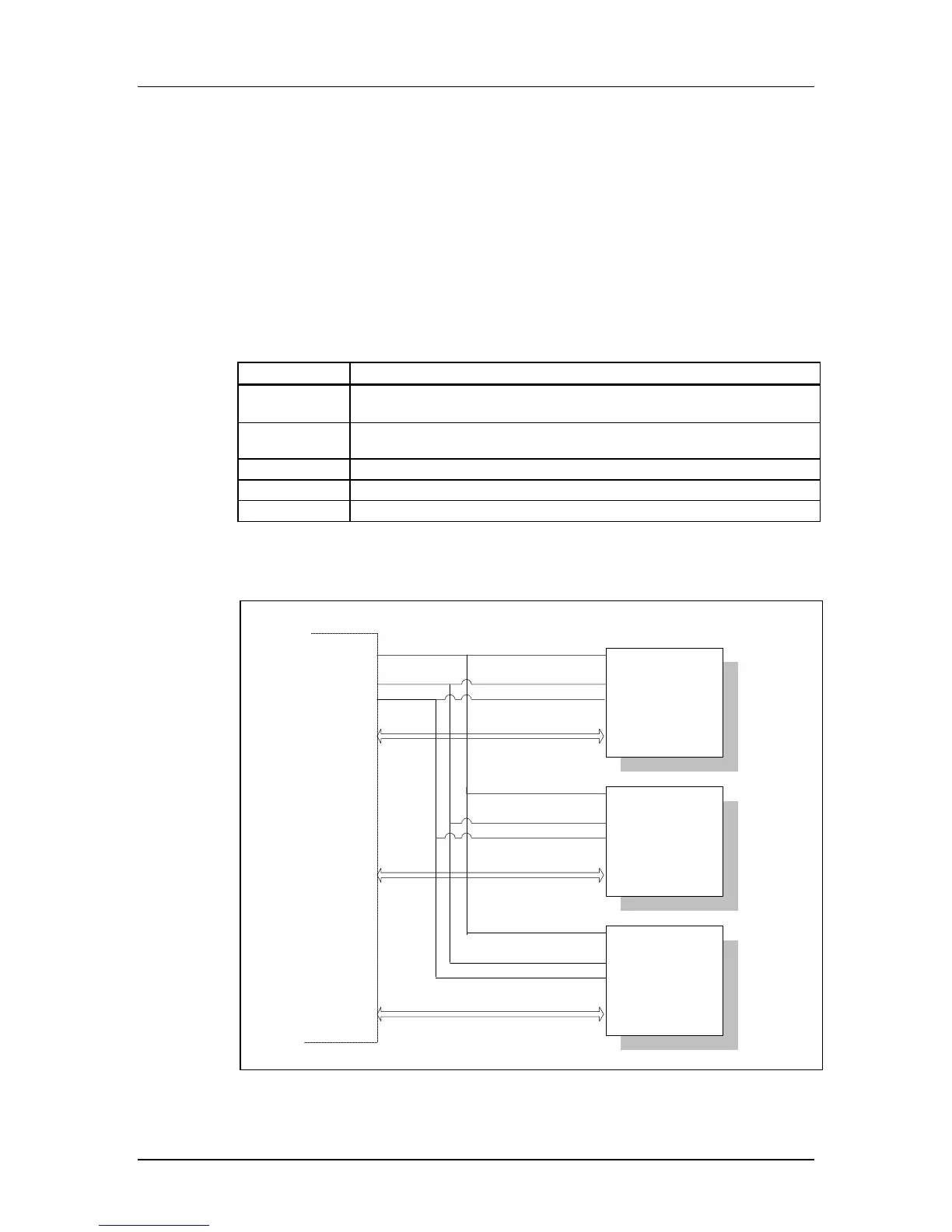
Figure 3-2 shows the bus topology of several cards with one host in SD Bus mode.
Figure 3-2 SD Card System Bus Topology
SD Memory
Card (A)
CLK
Vdd
Vss
D0-D3, CMD
SD Memory
Card (B)
CLK
Vdd
Vss
D0-D3, CMD
MultiMediaCard
(C)
CLK
Vdd
Vss
D0, CS, CMD
CLK
Vdd
Vss
D0-3(A),
CMD(A)
D0-3(B),
CMD(B)
D0-3(C)
CMD(C)
D1&D2 Not
Connected
 Loading...