Chapter 3 – SD Card Interface Description
Revision 2.2 SD Card Product Manual
© 2004 SanDisk Corporation 3-1 12/08/04
3 SD Card Interface Description
3.1 General Description of Pins and Registers
The SanDisk SD Card has nine exposed contacts on one side as shown in Figure 3-1. The
host is connected to the card using a dedicated 9-pin connector.
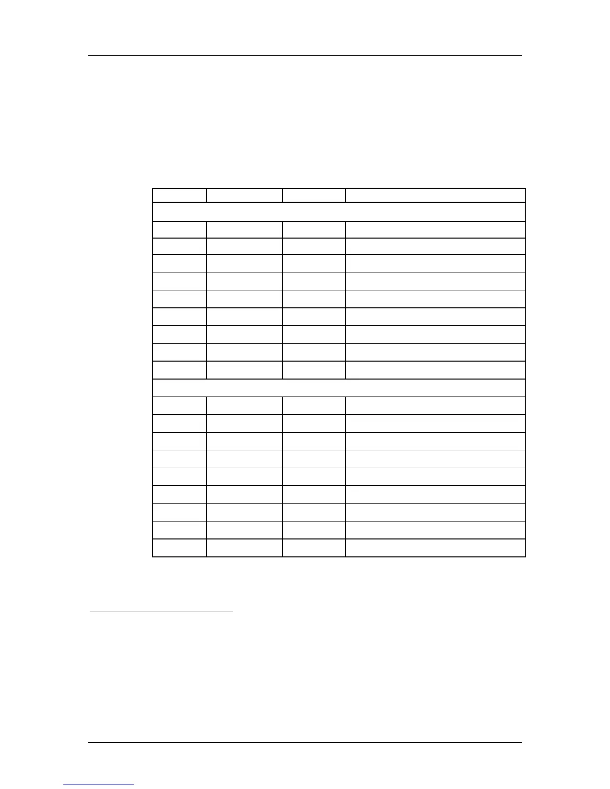
Table 3-1 SD Card Pad Assignment
Pin No. Name Type
1
Description
SD Mode
1 CD/DAT3
2
I/O
3
, PP Card detect/Data line [Bit 3]
2 CMD I/O, PP Command/Response
3 V
SS1
S Supply voltage ground
4 V
DD
S Supply voltage
5 CLK I Clock
6 V
SS2
S Supply voltage ground
7 DAT0 I/O, PP Data line [Bit 0]
8 DAT1 I/O, PP Data line [Bit 1]
9 DAT2 I/O, PP Data line [Bit 2]
SPI Mode
1 CS I Chip Select (active low)
2 DataIn I Host-to-card Commands and Data
3 V
SS1
S Supply voltage ground
4 V
DD
S Supply voltage
5 CLK I Clock
6 V
SS2
S Supply voltage ground
7 DataOut O Card-to-host Data and Status
8 RSV
4
--- Reserved
9 RSV
5
--- Reserved
1
Type Key: S=power supply; I=input; O=output using push-pull drivers; PP=I/O using push-pull drivers
2
The extended DAT lines (DAT1-DAT3) are input on power up. They start to operate as DAT lines after the
SET_BUS_WIDTH command. It is the responsibility of the host designer to connect external pullup resistors to
all data lines even if only DAT0 is to be used. Otherwise, non-expected high current consumption may occur due
to the floating inputs of DAT1 & DAT2 (in case they are not used).
3
After power up, this line is input with 50Kohm(+/-20Kohm) pull-up (can be used for card detection or SPI mode
selection). The pull-up may be disconnected by the user, during regular data transfer, with
SET_CLR_CARD_DETECT (ACMD42) command.
4
The ‘RSV’ pins are floating inputs. It is the responsibility of the host designer to connect external pullup resistors
to those lines. Otherwise non-expected high current consumption may occur due to the floating inputs.
5
Ibid.
 Loading...