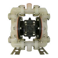
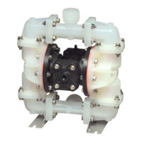
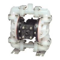
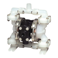
s15nmdl3sm-REV1207 Model S15 Non-Metallic Page 24
DIAPHRAGM SERVICING
To service the diaphragms first
shut off the suction, then shut off the
discharge lines to the pump. Shut
off the compressed air supply, bleed
the pressure from the pump, and
disconnect the air supply line from the
pump. Drain any remaining liquid from
the pump.
Step #1: See the pump composite
repair parts drawing, and the diaphragm
servicing illustration.
Using a wrench or socket, remove
the 16 capscrews (items 8), hex nuts
and washers that fasten the elbows
(items 17) to the outer chambers
(items 13). Remove the elbows with the
manifolds attached.
Step #2: Removing the outer
chambers.
Using a wrench or socket, remove
the 16 capscrews (items 10), hex nuts
and washers that fasten the outer
chambers, diaphragms, and inner
chambers (items 14) together.
Step #3: Removing the diaphragm
assemblies.
Use a 1½" (38mm) wrench or six
pointed socket to remove the diaphragm
assemblies (outer plate, diaphragm,
and inner plate) from the diaphragm rod
(item 31 by turning counterclockwise.
I n s p e c t t h e d i a p h r a g m
(item 15) for cuts, punctures, abrasive
wear or chemical attack. Replace the
diaphragms if necessary.
Step #4: Installing the diaphragms.
Push the threaded stud of the outer
diaphragm plate through the center
hole of the diaphragm. Thread the inner
plate clockwise onto the stud. Use a
torque wrench to tighten the diaphragm
assembly together to 480 in Lbs. (54.23
Newton meters). Allow a minimum of 15
minutes to elapse after torquing, then
re-torque the assembly to compensate
for stress relaxation in the clamped
assembly.
Step #5: Installing the diaphragm
assemblies to the pump.
Make sure the bumper (item 5) is
installed over the diaphragm rod.
Thread the stud of one diaphragm
assembly clockwise into the tapped
hole at the end of the diaphragm rod
(item 31) until the inner diaphragm plate
is ush to the end of the rod. Insert rod
into pump.
Fasten the remaining outer chamber
(item 13) to the pump, using the
capscrews (items 10), hex nuts and at
washers and tighten.
Make sure the bumper (item 5) is
installed over the diaphragm rod.
Thread the stud of the other
diaphragm assembly clockwise into the
tapped hole at the end of the diaphragm
rod (item 31) make sure the 2nd
diaphragm assembly is tight enough
that the inner plate is ush to the end
of the rod. The bead of the end of the
diaphragm should t into the groove of
the inner chamber.
Read these instructions
completely, before in-
stallation and start-up.
It is the responsibility of
the purchaser to retain
this manual for reference. Failure to
comply with the recommendations stated
in this manual will damage the pump, and
void factory warranty.
IMPORTANT
Fasten the remaining outer chamber
(item13) to the pump, using the
capscrews (items 10), hex nuts and
at washers.
Step #6: Re-install the elbow/
manifold assemblies to the pump, using
the capscrews (items 8), hex nuts and
at washers.( Ref.pg 12)
The pump is now ready to be
re-installed, connected and returned to
operation.
OVERLAY DIAPHRAGM SERVICING
The PTFE overlay diaphragm
(item 16) is designed to t over the
exterior of the standard diaphragm
(item 15).
Follow the same procedures
described for the standard diaphragm
for removal and installation.