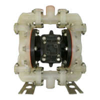
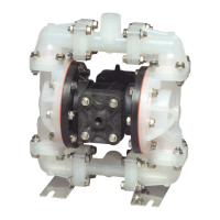
s15nmdl3sm-REV1207 Model S15 Non-Metallic Page 15
SPILL CONTAINMENT CONCEPT
The spill containment option
prevents the air end components from
being contaminated or damaged when
a pumping diaphragm ruptures while
pumping caustic or toxic materials. It
also helps to protect the environment.
With the installation of optional leak
detectors (either mechanical or
electronic) the diaphragm rupture can
be detected. The pump can then be shut
down and repaired before any caustic
or toxic materials can enter the air end
and be exhausted into the surrounding
environment.
OPTION DIAPHRAGM SERVICING
To service the diaphragms first
shut off the suction, then shut off the
discharge lines to the pump. Next shut
off the compressed air supply, bleed
the pressure from the pump, and
disconnect the air supply line from the
pump. Drain any remaining pumped
liquid from the pump. Remove the pump
before servicing.
Next, drain the uid from the spill
containment chambers. This can be
done by removing the bottom plug
(item 46 )from each spill containment
chamber.
After the fluid from the spill
containment chambers has been
drained, the wet end components can
now be removed. See diaphragm
s e r vicing se c t i o n fo r d e t a i l e d
instructions. The spill containment
option has two additional virgin PTFE
pumping diaphragms (item 41). These
diaphragms are installed with the
natural concave curve toward the
outer chamber (items 13 from the pump
assembly drawing).
FILLING CHAMBERS WITH LIQUID
THE CHAMBERS ARE FILLED WITH
WATER AT THE FACTORY.
If you prefer to substitute another
liquid, to prevent system contamination
consult the factory rst to determine
compatibility of the substitute with pump
construction.
Follow the steps listed here to
replace the liquid in the pump after
disassembly or liquid loss:
1. Drain the fluid in the spill
containment chambers by removing
the bottom two boss plugs (items 46).
Replace the bottom two boss plugs after
the uid is drained.
2. Remove the eight capscrews (item
10) fastening the discharge manifold
and elbows to the outer chambers
(items 13). The discharge manifolds and
elbows can now be removed.
3. Remove the top two boss plugs
(items 46). The spill containment
chambers are lled through the exposed
ports.
4. Install safety clip (item 1-K) into
the smaller unthreaded hole in one
end cap (item 1-E). This locks the valve
spool to one side, keeping the pump
from shifting. Apply air pressure to the
air distribution valve.
5. Face the side of the pump with
the installed safety clip. If the safety clip
is installed in the top end cap, ll the left
spill containment chamber. If the safety
clip is installed on the bottom end cap, ll
the right spill containment chamber. The
volume of uid is 1950 ml (65.9 . oz.).
It is important that the exact amount of
uid is used. Too little or too much uid
causes premature diaphragm failure
and erratic pumping.
6. Loosely reinstall one boss plug
(item 46) to the lled spill containment
chamber.
7. Shut off air supply. Remove safety
clip. Adjust the air line regulator so that
air pressure slowly lls the pump. The
diaphragm expands, forcing the uid
in the chamber to be slowly displaced.
When the pump shifts to the opposite
side, quickly install the safety clip.
8. Loosen the top boss plug on the
lled chambers. This allows uid in the
chamber to purge trapped air from the
chamber. This can be seen by watching
the column of uid in the sight tube.
When uid appears at the top of the
port, quickly tighten the boss plug. Fluid
loss of 1 to 2ml is acceptable.
9. Tilt the pump so the uppermost
pipe tee (item 48) is in the vertical
position. Loosen the pipe plug (item
45). This will allow trapped air to
purge through the pipe tee. When uid
appears at the tee opening, reinstall
the pipe plug.
NOTE: If all air is not purged using
this procedure, remove the check valve
components from the top port of the
outer chamber (item13). Apply manual
pressure to the pumping diaphragm by
inserting a blunt instrument into the top
port of the outer chamber and applying
pressure to the diaphragm. Loosen the
pipe plug (item 45) allowing the uid
to purge any remaining trapped air.
Reinstall the plug.
Read these instructions
completely, before in-
stallation and start-up.
It is the responsibility of
the purchaser to retain
this manual for reference. Failure to
comply with the recommendations stated
in this manual will damage the pump, and
void factory warranty.
IMPORTANT
10. Repeat steps 5 through 9 to ll
opposite spill containment chamber.
11. Reinstall the check valve
components, discharge manifold and
elbows to the pump. The pump is now
ready for operation.