4
TUNER 2 TUNER 1
LNB in
14/19V
350mA Max
ETHERNET USB HDMI
TV VCR
DC 12V 2.5A
S/PDIF
11 12 13 14 15 16
8 9 10
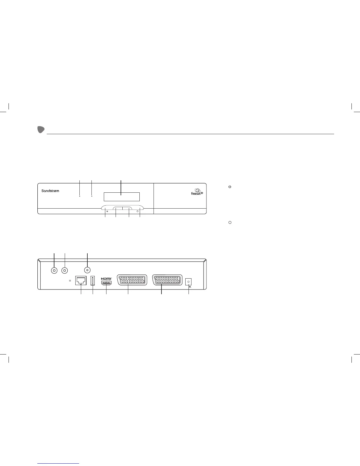
1. Power Indicator
• Lights up green when the unit is on.
• Lights up red when the unit is in Standby mode.
2. Recording Indicator
Indicates when live TV is recording.
3. LED Display
Displays the current channel number.
4. Button
Switches the unit on and o.
5. CH+ Button
Selects the next channels.
6. CH- Button
Selects the previous channels.
7.
R
Button
Records live TV.
8. TUNER 2 Socket
Connects to the satellite dish.
9. TUNER 1 (LNB in) Socket
Connects to the satellite dish.
10. S/PDIF Socket
Connects to a digital audio system.
11. Ethernet Socket
Connects to the Internet.
12. USB Socket
Connection port to upgrade.
13. HDMI Socket
Connects to a HD-ready TV.
14. TV SCART Socket
Connects to a non-HD TV.
15. VCR SCART Socket
Output/input connection to a video recorder or DVD recorder.
16. Power Socket
Connects the mains adapter.
Rear View
Front View
Power Rec
CH+ CH- R
1 2 3
4 5 6 7
Product Overview
SHDFSAT12_IB_V2.indd 4 13/06/2013 12:19



 To Next Page